Facebook
 Google
 GitHub
 Linkedin
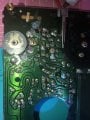
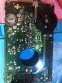
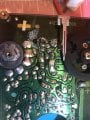
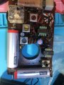
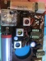
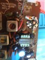
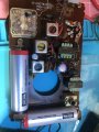
I am a newbie here and am trying to troubleshoot a Sanyo RP-1350 with six transistors. Vintage 79-80 I think. It runs 3V. I can inject a signal into the base of all transistors and it does come to the speaker. The first transistor is weak but it does go all the way through. The radio does not receive any stations at all. When I got it one of the antenna wires was broken. I repositioned it to the base of the first transistor. I apologize I don't have a schematic but that seemed appropriate. There were already two leads going to the tuning capacitor.
I have searched and cannot find a schematic for this model. I am thinking of taking out some of the components at the front end of the circuit and testing them but worried about damage. At the Collector of the first transistor I did measure 2.6V leaving it and I think .7 v going in the base. I am puzzled. I know the radio is not worth much but I am using it to try to learn.
I have searched and cannot find a schematic for this model. I am thinking of taking out some of the components at the front end of the circuit and testing them but worried about damage. At the Collector of the first transistor I did measure 2.6V leaving it and I think .7 v going in the base. I am puzzled. I know the radio is not worth much but I am using it to try to learn.