Ripple looks like noise?

Status
Not open for further replies.

Thread Starter

davidowens

Joined Oct 3, 2014
12
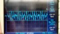
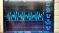
When I'm measuring ripple it looks like noise
Can ripple look like noise or is ripple noise?

Mostly I'm use to seeing ripple as a sawtooth discharging waveform it doesn't look like noise but other AC power supply ripple looks like noise

How does a tech know if this is AC ripple or noise?
 

Attachments

MrChips

Joined Oct 2, 2009
30,823
Depends on one's definition of noise. 50Hz, 60Hz and 400Hz ripple can also constitute noise.
If you are looking for ripple, then sync your scope to line frequency. Otherwise noise is usually random.

By the way, Dan, Dave, David or Vinny, your little game is exposed.
 

Thread Starter

davidowens

Joined Oct 3, 2014
12
60hz ripple looks like a trianglish discharging waveform

400hz ripple look likes random noise to me

If you are looking for ripple, then sync your scope to line frequency.
There is different trigger modes on the O-scope:
With the external trigger or set the trigger to channel#1 or trigger to line?
 

vk6zgo

Joined Jul 21, 2012
677
60hz ripple looks like a trianglish discharging waveform

400hz ripple look likes random noise to me

There is different trigger modes on the O-scope:
With the external trigger or set the trigger to channel#1 or trigger to line?


If you are using a fullwave rectifier,your "ripple" should be 120Hz ,with the waveform you describe.
A halfwave rectifier will give you 60Hz "ripple".
You may also see 60Hz which looks like a sinewave this is what you would normally call "mains hum"---this is not "ripple" from your power supply..

Where do you get the 400Hz from?
I was thinking of 3 phase supplies at 60Hz,but that would be 180Hz in the halfwave case,& 360 Hz in the fullwave case.
The other possibility is military 400Hz power supplies.
Single phase,these would give you 400Hz "ripple for a halfwave rectifier & 800 Hz for a fullwave rectifier.

If you set your 'scope to trigger from "line",it will trigger at the 60Hz mains rate.
If the signal you are observing is stable,it is derived from the mains frequency,
 

Thread Starter

davidowens

Joined Oct 3, 2014
12
Single phase,these would give you 400Hz "ripple for a halfwaverectifier & 800 Hz for a fullwave rectifier.
Yes the power supplies are 400hz and others are 800hz

A 400hz ripple looks like noise to me and also the 800hz ripple looks like noise to me

How would you set up the O-scope to measure 400hz or 800hz ripple?

You may also see 60Hz which looks like a sinewave this is what you would normally call "mains hum"---this is not "ripple" from your power supply..
Ok maybe i'm confusing the two

How do you know what is ripple or hum?

Because I set my Oscope to AC Coupling on channel#1 and put the Oscope triggering to trigger to Channel#1 input. The waveform looks like a sine waveform in millivolts, is this ripple or hum?
 

NorthGuy

Joined Jun 28, 2014
611
Depending on the ratio of the sampling drequency of your scope to the frequency of the ripple, a relatively regular vaweform may look like a noise.
 

Thread Starter

davidowens

Joined Oct 3, 2014
12
I have tried the Average Mode and Bandwidth mode to take away the noise out of the ripple, it doesn't help much when measuring 400hz or 800hz ripple
 

Thread Starter

davidowens

Joined Oct 3, 2014
12
On the output of the regulators

Measure the Positive supply ripple on the positive regulators output after the filter caps
Measure the Negative supply ripple on the negative regulators output after the filter caps

What is VR2 diode for? not sure why the negative supply only has a VR2 diode because the positive regulator doesn't have one, any reasons why?

Q19 and Q20 are series pass transistors

Not sure why the Negative regulator has two series pass transistors compared to the positive regulator only has one series pass transistor Q21 , any reasons why?

Why does the Negative Regulators input uses the Positive regulators output?

Most dual power supplies I have seen both positive and negative regulators go Direct to the diode rectifier

but this power supply uses the positive regulators output as the negative regulators input, any reasons why?
 

Attachments

Status
Not open for further replies.
Top