rheostat in voltage divider circuit

Thread Starter

user4592357

Joined Nov 13, 2016
20
i need to determine the voltage ranges for voltage divider circuits that contain rheostats. here are what i got for each circuit (i've just learned about these so please correct me if i'm wrong)

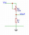
this is the first circuit. here's what i think
1) if R2 = 0 ⇒ Vout = Vin / R1
2) if R2 = R2max ⇒ Vout = Vin / (R1 + R2)
Capture.PNG

this is the second circuit and my results
1) if R1 = 0 ⇒ Vout = Vin / R2
2) if R1 = R1max ⇒ Vout = Vin / (R1 + R2)
Capture.PNG

for the last circuit i need to prove why is the range 0-Vin
1) R1 = 0 ⇒ Vin and Vout are connected so Vout = 0
2) R1 = R1max ⇒ (i can't prove this, i don't think it is Vout = Vin / R1)
Capture.PNG

any help would be appreciated. thanks
 

Attachments

wayneh

Joined Sep 9, 2010
17,496
1) if R2 = 0 ⇒ Vout = Vin / R1
Nope. Think about it: Vout is connected directly to ground through R2=0. Can Vout be anything other than zero?
2) if R2 = R2max ⇒ Vout = Vin / (R1 + R2)
No, you've done the algebra wrong. Try Vin • R2/(R1+R2).
1A) if R1 = 0 ⇒ Vout = Vin / R2
Again, if Vout is connected directly to Vin, how can it be anything else but identical to Vin?
2A) if R1 = R1max ⇒ Vout = Vin / (R1 + R2)
Similar to #2 above.
1B) R1 = 0 ⇒ Vin and Vout are connected so Vout = 0
It's undefined, since you have a voltage source connected directly to ground. Oh wait, there's no connection to the wiper? Then this is equivalent to a 100k resistor between Vin and ground and Vout which appear to be connected? Vout is thus ground and it makes no difference where the wiper is set.
2B) R1 = R1max ⇒ (i can't prove this, i don't think it is Vout = Vin / R1)
Same as above
 

hrs

Joined Jun 13, 2014
394
The right equation to use is Vout = Vin * (R2 / (R1 + R2)).

If you just look at the first circuit and move the wiper all the way up (R2 = 0) you can see that you have shorted Vout to ground, thus Vout = ground. The formula is in agreement with this.
 

Thread Starter

user4592357

Joined Nov 13, 2016
20
thanks for the answer, it was helpful. i slightly don't understand the explanation for the 3rd case. are these correct?
1) when R1 = 0 ⇒ Vin and Vout are connected, so Vout = 0?
2) when R1 = R1max ⇒ there is a resistor between Vin and Vout and thus a voltage difference so I = Vin / R1 and Vout = I * R1 = Vin?

and what difference would it make if there was a connection to the wiper?
 
Last edited:

djsfantasi

Joined Apr 11, 2010
9,156
Look at the schematic closely. Can R1 be 0 ohms? Where is the wiper connected?

But even easier, what potential is Vout directly connected?
 

Thread Starter

user4592357

Joined Nov 13, 2016
20
oh well, Vout is connected to the ground so Vout = 0. but in which case? and then how could Vout be equal to Vin if it's connected to the ground?
 

Thread Starter

user4592357

Joined Nov 13, 2016
20
no because it's connected to the ground. but in class we wrote that with that circuit, the range of Vout is 0÷Vin but Vout is connected to the ground so how can it ever be Vin?
 

Thread Starter

user4592357

Joined Nov 13, 2016
20
we wrote that in class and that's why i asked, how did they write that? but yeah surely it's always connected to the ground and is always 0
 

djsfantasi

Joined Apr 11, 2010
9,156
The horizontal line should be the ground.
Yes @ScottWang, I agree. I was making that assumption that the horizontal green line was ground. This graphic illustrates what I was assuming. It's similar to yours and differs only in that it uses the red dot as a junction, similar to the TS diagrams where the "rheostat" connections are made.

Capture (1a).png

Basically, the question comes down to how accurate the original drawings were? Which one below is correct?
Capture (1c).png
 

ScottWang

Joined Aug 23, 2012
7,397
Yes @ScottWang, I agree. I was making that assumption that the horizontal green line was ground. This graphic illustrates what I was assuming. It's similar to yours and differs only in that it uses the red dot as a junction, similar to the TS diagrams where the "rheostat" connections are made.

View attachment 120956

Basically, the question comes down to how accurate the original drawings were? Which one below is correct?
View attachment 120957
The right one is correct.

I'm not sure what the TS want to do, but I will do as what I modified in #13, they just like the volume control of amplifier.
 

Thread Starter

user4592357

Joined Nov 13, 2016
20
i see why there needs to be a junction but why are circuits in #13 correct? i mean, why isn't a connection to the wiper needed, and why is Vout the same as rheostat wiper? thanks
 

djsfantasi

Joined Apr 11, 2010
9,156
I'm sorry. I am baffled by your last response. In post #13, both circuits have a connection to the wiper. Yet you ask why isn't a connection needed?
 
Top