how to convert 0-10 volts signal to a rheostat from 0 to 100 kOhms

Thread Starter

NarcisCC

Joined Oct 4, 2024
4
Hello,

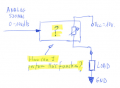
I need to convert a signal from an analog output of 0-10 volts to a rheostat that goes from 0 to 100 kOhms. See the drawing in the attached file.
I don't have any idea of how to achieve that or if there's some pcb in the market prepared to perform this function. I Know there are Digipots or DAC's but i don't know how to implement in my circuit.

Someone can help me ? Thank you in advance
 

Attachments

Thread Starter

NarcisCC

Joined Oct 4, 2024
4
Hi Narcis.
Welcome to AAC.
Are you trying to control the current through the load using a 0v to 10V source,
E
The control has its own electronics. It is supplying me the 10 volts. So I just need to control a Rheostat to give it more or less current.
 

Ya’akov

Joined Jan 27, 2019
10,226
Welcome to AAC.

When you say rheostat what do you mean in practice? What is the application for it? How much current will it be expected to handle?

Could you explain what problem this is intended to solve?
 

Thread Starter

NarcisCC

Joined Oct 4, 2024
4
Welcome to AAC.

When you say rheostat what do you mean in practice? What is the application for it? How much current will it be expected to handle?

Could you explain what problem this is intended to solve?
The problem is that I have an analog output of 0-10 volts that comes from a PLC. With this signal I have to control the brightness of lights which they have its own brightness controller. I mean I have two separate circuits in the light. The power for light is one circuit and the control of brightness is another circuit. They are independent. But the point is that the brightness control sinks 10 volts. I can control the brightness of the light manually, just with a simple Rheostat it works. The point is that i need to do it from a PLC which delivers 0 to 10 volts and i don't know how to convert these volts in a proportional resistance to control the brightness.
About the current to handle is around 100 mA.
When I say Rheostat I mean just a potentiometer which uses only 2 pins instead of 3 pins. See the attached circuit of figure 4.

Thank you
 

Attachments

BobTPH

Joined Jun 5, 2013
11,489
You do not necessarily need to control a resistance. The pot is usually (not always) used to provide a variable voltage.

Do you have any info on the dimmer board you are using? A schematic would be really helpful.

It is possible that you can disconnect one wire of the pot and connect it to the control voltage and make it work, but we have to know how the pot is used and at what voltage.
 

schmitt trigger

Joined Jul 12, 2010
2,056
If I recall correctly, 0 - 10v is a standard interface control voltage for light controllers. Many light controllers directly support this.

A quick Google search shows a myriad controllers with this interface.
 

MisterBill2

Joined Jan 23, 2018
27,366
The talk is horribly confusing the problem. When the TS tells us that:" the point is that the brightness control sinks 10 volts." That tells me that first, the lights brightness is controlled by a zero to ten volt signal, and second, that the brightness control input has some sort of internal pull up.
So now we need for the TS to provide a bit of information, because it looks to me like the solution might be VERY SIMPLE and EASY!! If the TS has any information about the control, such as instructions or a data sheet, that will help a lot. It might be as simple as switching off the internal 10 volt pull up and connecting the analog output of the PLC to the brightness control input, along with connecting the commons to each other. It SHOULD be that simple!!
 
Top