Facebook
 Google
 GitHub
 Linkedin
Hi everyone,
I receive C-Band signals from 1.9m dish via a C-Band PLL LNBF. This one has a L.O. frequency of 5.150GHz.
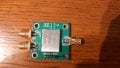
I intend to switch the signal out of the LNB alternatively to two different receivers. The switch used for this is
the HMC435 module SPDT RF non-reflective switch. Making some isolation ports measurements with a steady signal (the satellite beacon frequency 1.199GHz after down-conversion) the module did not respond to what I was expected. From the datasheet I would expect an isolation of approximately -62 dB. The attached pix indicate the various measured values:
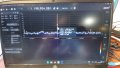
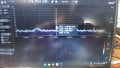
Direct connection (i.e. without SPDT switch) -56.7dBFS (FS = full scall)
Output A (i.e. trough SPDT port A operational) -55.9 dBFS
Output B (i.e. as Output A but measured on port B) -60.5dBFS
The isolation between port A and port B is only 4.6dB which is far away from the specs.
Doing measurements with port B operational provides almost same figures. So I suspected a faulty module, but since I have two of them, I repeated the test with the second one and unfortunately it provides figures in the same range.
I am really puzzled. What's wrong? Could someone give me a start of explanation.
Many thanks
I receive C-Band signals from 1.9m dish via a C-Band PLL LNBF. This one has a L.O. frequency of 5.150GHz.
I intend to switch the signal out of the LNB alternatively to two different receivers. The switch used for this is
the HMC435 module SPDT RF non-reflective switch. Making some isolation ports measurements with a steady signal (the satellite beacon frequency 1.199GHz after down-conversion) the module did not respond to what I was expected. From the datasheet I would expect an isolation of approximately -62 dB. The attached pix indicate the various measured values:
Direct connection (i.e. without SPDT switch) -56.7dBFS (FS = full scall)
Output A (i.e. trough SPDT port A operational) -55.9 dBFS
Output B (i.e. as Output A but measured on port B) -60.5dBFS
The isolation between port A and port B is only 4.6dB which is far away from the specs.
Doing measurements with port B operational provides almost same figures. So I suspected a faulty module, but since I have two of them, I repeated the test with the second one and unfortunately it provides figures in the same range.
I am really puzzled. What's wrong? Could someone give me a start of explanation.
Many thanks
Attachments
-
 1.6 MB Views: 6
 -
 1.4 MB Views: 6
 -
 1.4 MB Views: 5