 Facebook
 Google
 GitHub
 Linkedin
I have made a custom board using the Texas Instruments CC1350 Launchpad (Development board) reference design.
Because my PCB layout is different from the TI's Development board. I need to tune the antenna.
How do I calculate the values of the three components of a Pi-Network (matching network) without a VSR Meter or a Spectrum Analyzer. I can read the RSSI though by using another such a Development board as Receiver and the custom board as Transmitter.
Is there a software available, like Genesys from Keysight, that could aid in defining the values for those components in a Pi-network.
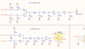
In the attachment you will find the schematic of my custom board. The RF section is a copy of the Development board. Why are there so many components after the Balun? There must be a filter, a Pi-network and a DC blocking capacitor, right?
Because my PCB layout is different from the TI's Development board. I need to tune the antenna.
How do I calculate the values of the three components of a Pi-Network (matching network) without a VSR Meter or a Spectrum Analyzer. I can read the RSSI though by using another such a Development board as Receiver and the custom board as Transmitter.
Is there a software available, like Genesys from Keysight, that could aid in defining the values for those components in a Pi-network.
In the attachment you will find the schematic of my custom board. The RF section is a copy of the Development board. Why are there so many components after the Balun? There must be a filter, a Pi-network and a DC blocking capacitor, right?
Attachments
-
 39.9 KB Views: 14


