Reviewing schematic: Low Power Ground Fault Interrupter

Thread Starter

Blue_Electronx

Joined Jun 10, 2019
112
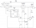
Schematic attached is found in the datasheet of the IC RV4145A. It's a low power controller for AC outlet ground fault interrupters. They have two versions of the schematic, a two-wire configuration, and a three wire configuration. The picture attached is the three wire version which has an extra current transformer. The two-wire version only has a transformer and it's not designed to detect grounded neutral faults. I'm trying to study the schematic, and this is my question:

Does the bridge rectifier have two purposes here? Supply the IC and close the path through the SCR for the solenoid. Is it right?


Attachments

Dodgydave

Joined Jun 22, 2012
11,395
Yes, the bridge rectifier is being used with the solenoid in series so that the thyristor can operate on AC, and feed the ic. Once the thyristor fires the solenoid will remove power from the load.
 

Thread Starter

Blue_Electronx

Joined Jun 10, 2019
112
Thank you. I have one more question: when is it better to use three wire configuration over the two-wire? The two wire setup does not detect grounded neutral faults, but is it a big deal? Hot-grounded faults are more common, right?
 

Thread Starter

Blue_Electronx

Joined Jun 10, 2019
112
Good. I think I got the idea. About the other components: CF is filter capacitor, C2 for snubber, C1 coupling capacitor. The test button just causes an imbalance in purpose to check if the solenoid trips. Correct me if I'm wrong.
 
The neutral-ground detection is in the event of the neutral becoming disconnected from earth ground at the transformer. This is not a frequent occurrence but I have had it happen on 3 occasions at 3 different homes I have occupied. Maybe I'm just unlucky.
For maximum safety I would use the three wire version. It might save your life.
 
Top