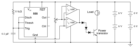
I am looking for a circuit diagram for a pwm circuit that is controlled by a variable resistor. what I am looking to do is control a peltier cooler by a temperature sensing resistor. the voltage source I have is automotive 12v-15v dc.
You could adapt the circuit shown here - you would use your variable (sensing) resistor in combination with a fixed resistance of suitable value to replace the control potentiometer in the circuit shown in the link.
I've done these, you just need thermistor and one comparator as in a standard on/off temperature controller, but then you add feedback so it oscillates around the comparator setpoint. Perfect PWM that changes duty to keep the temperature steady.
The addition of a small cap from comparator input to ground lets you tune the frequency to (say 4kHz) fast enough to save the peltier from thermal shock and slow enough to reduce switching losses.
RB: I am building this circuit and you mentioned a cap on the input of the comparator to make the switching freq around 4k. what size cap would you recommend? sorry, I can assemble and fix circuit, but I don't know enough to design them.
The 1458 is an old and slow opamp that can't source much current, and you are trying to use it to drive a power transistor. That's just not going to work very well.
I recognize this circuit from the AAC experiments volume. It would work, but a resistor in line with the diodes should be there. These experiments are verified (as in they have been built), but many of them aren't exactly practical. I'm not excepting my entries in this.
bill, the circuit is the one you recommended from the experiments section.
I am trying to drive a power transister that can carry a 10A load at a frequency that will not damage my peltiers I am trying to control.
if the 1458is old, slow and cannot handle current, could you recommend one that could?..
I am going to be driving two large peltier coolers here
there are actually 2 peltiers in each run in parallel.
ideally the circuit would have 2 temp sensors to compare and use the resistant differance to control the peltiers.
check input temp, if temp increasing then increase cooling, check output temp for goal, if at goal then maintain if not increase cooling. however, as long as I have a temp sensor I can make the circuit work by monitoring the over all output temps and adjust the cooler to compensate. I do know that I will have to wire in a bypass to give the peltiers a full power on ocassion for fast cooling as necessary.
If you are using a 12VDC power supply you could use MOSFETs. I'm working on a new section for my article, you can read about how to use them in Chapter 10 in my work in progress area, LEDs, 555s, Flashers, and Light Chasers (forum edition). You will need to loose the op amps though. A 555 will drive a MOSFET well, put a 100Ω resistor between the output of the 555 and the gate.
MOSFETs require almost no current on the gate past a single surge when switching. A BJT requires some current on the BE to keep them turned on. For large current applications this can be a major deficit.

 Facebook
 Google
 GitHub
 Linkedin