Resisting path to ground and keeping current flowing.

Thread Starter

dandy1

Joined Sep 30, 2017
178
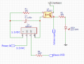
I have a situation where I am taking off an ignition coil to read RPMs. And to kill two birds if i ground out the primary it kills the ignition. Its a strange set up i know but this is how it is.
Ignition sensor.GIF
R3 was choosen as this allows at least some current to allow the circuit to work, and hence get a reading on the arduino. the circuit works a charm and thanks to the boys at Arduino.cc. at the same time providing enough resistance so that the ignition finds its way to the spark plug, rather than grounding. Or to put it better to allow the engine to start as you can tell there is more resistance as its harder to start.

so its at the point where there is just about enough current for the circuit to work and just about enough resistance to allow it to start.
the cap was placed in as a presumptive measure to combat noise before R3 and has stayed ever since, all i can say is that it works and if i remove it -it doesn't.

What could i improve to ease the burden on the primary whilst still allowing current into the circuit.


Thanks
 

LesJones

Joined Jan 8, 2017
4,174
Is this the older type of ignition system with a coil, a contact breaker and a distributer (Assuming it is a multi cylinder engine or is it something different ? If so is the signal "primary in" from the junction of one side of the coil and the contact breaker ? The lable "3.2 volts AC" does not seem to fit this type of system.

Les.
 

Thread Starter

dandy1

Joined Sep 30, 2017
178
Sorry i should ave explained.

The system is a simple 7 hp generator with a tiny coil, the primary connection provided is for the the purpose of grounding the coil as to shut off the engine. i think (guessing here) that the low voltage is actually a trigger coil that fires the primary
 

LesJones

Joined Jan 8, 2017
4,174
So it is a sytem were the coil is situated inside the flywheel and is powered by magnets inside the flywheel rather than from a battery. I would not try to drive the opto isolator directly from this signal. The signal from the coil primary will be a fast spike of a few hundred volts. The pulse may be positive or negative depending on the design of the magneto. I would try using a small 240 volt to 12volt tranformer to step this pulse down to drive the base of a transistor via a high value resistor. You would also need a diode between the base and emitter of this transistor to protect it from reverse polarity. The collector of the transitor would be connected directly to the input of the arduino together with a resistor (Say 10K) to + 5 volts. If you do not have an oscilloscope to check the polarity of the pulse from the transformer you would have to try reversing the connections to the transformer if it did not work. One thing you could try with you original circuit is to remove the LED and replace R2 with a 1K resistor to ground. This should allow you to increase the value of R3 by a resistor about 4 times it's present value.

Les.
 

Thread Starter

dandy1

Joined Sep 30, 2017
178
Hi Les :)oops:) sorry again.

I have tried this circuit (i should have explained- again sorry).

heres a snippet from the serial mointor:

Code:
1321    :    15319    RPS: 60
1311    :    15055    RPS: 61
1321    :    15343    RPS: 60
1116    :    15064    RPS: 61
1319    :    15456    RPS: 59
1175    :    15148    RPS: 61
1313    :    15430    RPS: 59
1322    :    15310    RPS: 60
1231    :    14953    RPS: 61
1312    :    15432    RPS: 59
Average RPS: 60
1265    :    15175    RPS: 60
1318    :    15465    RPS: 59
1229    :    15075    RPS: 61
1317    :    15385    RPS: 59
1343    :    15025    RPS: 61
1311    :    15470    RPS: 59
1391    :    15105    RPS: 60
1316    :    15316    RPS: 60
1204    :    15036    RPS: 61
1309    :    15416    RPS: 59
Average RPS: 59
on the left is the result of pulseIn, HIGH
then its pulseIn, LOW
RPS is the sum of them both and the division into 1000000uS

So it looks like that it undoubtedly gives a positive pulse for a milli or so. Even if there is a large spike it hasn't yet killed the opto tho i don't know exactly what voltage and hence current is flowing.

Yes I will be removing the LED as it only served as a feedback mechanism before i attached the arduino.

Arduino circuit is completely isolated from the rectifier and if i increase the value of R3 it effectively stops the current flow through the rectifier and hence the triggering of the opto.

I should have given a more thorough explanation i can only apologise.

my initial feelings are that i am putting the coil under additional load and inducing amperage into the coil, which its not designed for, so i am looking into ways to reduce that if possible, your transformer theory will try if i get problems with the opto (could a voltage divider serve for this purpose)
 

Attachments

LesJones

Joined Jan 8, 2017
4,174
The circuit in post #6 would put a heavier load on the pulse from the ignition coil and would probably prevent the engine from running. In your original circuit you had a 2667 ohm (Which seems a very strange value resistor. ) in series so it would not load the pulse as much so you would get a high enough voltage from the ignition coil secondary to still give a spark. (This resistor limits the current though the emitter part of the opto.) Increasing the value of this resistor will give a better spark so the engine will start easier but from what you have said the arduino no longer sees the pulses. This is because the light pulse from the emitter in the opto is weaker due to the reduced current pulse. As the light pulse is weaker it does not make the photo transistor part of the opto conduct as much so the output pulse is smaller and not detected by the Arduino. If the value of R2 is increased it will increase the output voltage pulse for the same value of current pulse. This should enable the Arduino to be able to detect it again. Another thought. If the generator is an AC output you could just use the frequency of the output to measure the speed. (Via a small transformer to reduce the voltage.

Les.

Les.
 

Thread Starter

dandy1

Joined Sep 30, 2017
178
Hi Les

Thanks for your input, and your patients. So i will try larger resistor for R2 to help improve to spark, hopefully this will allow more headroom with the potentiometer (not designated as on the schematic) at R3. The Idea of reading from the spark is to limit the amount of physical wires running into my board hence the two birds with one stone - so i also use this to kill the engine, via a separate opto. The transformer method is a no go at the moment as the board measures just 47mm x 50mm and its already populated densely (H bridge/photorelays/micro) not even on the back as there are two regulator circuits there, I did have it set up that it reads the charge coil feeding the battery but the extra wires were a hassle, and to be honest it was a good system but so many wires made a real mess. Im hoping to reduce the feeds from 8 to 4. Using photo relays instead of mechanical relays got rid of 2 wires and this will hopefully get rid of the charge coil sensor and in the meantime add an RPM meter.

I've got a schematic if your interested (i mean if you got time and want to be critical)

cheers
 

Thread Starter

dandy1

Joined Sep 30, 2017
178
Putting 2.2k on R2 allowed for 3.6k on R3
Putting 10K on R2 allowed for 10k on R3,
there appears to be a relationship there.

Anyways the headroom now lets the signal be read while having no fear of grounding out the ignition.

Another concern is there any significant current passing through the bridge? ill be looking to use a small package (mb6s) if its insignificant. If the voltages (3.2) are correct it should'nt be a problem right? I don't really know about the bridge resistances if there are any.

Also the opto (pc817) and handle 50mA on its output, do you think it possible to use this to ground the ignition(after rectifying).
 
Last edited:

LesJones

Joined Jan 8, 2017
4,174
There probably is a limit to how high you can make R2. Reason 1. There may be a point at which the transfer ratio of the opto coupler drops to a low value for very low current inputs. Threre are probably graphs on the data sheet that would give you this information. Reason 2 . R2 is pulling the arduino input low. If weak pullups are enabled on the atmel chip in the Arduino then if R2 is too high it will not be able to pull the input low.
If you ground pin 3 of the bridge directly the could be currents up to a few amps. If we assume the pulses from the ignition circuit are about 200 volts then you could add a series resistor to limit the current. To limit this to 50 mA the resistor would have to be 4K which is higher than the 2.667 K that you found would still allow the engine to run so you would exceed the current rating of the opto. Also it is probable that when the opto was in it's off state the voltage would exceed it's voltage rating.

Les.
 
Top