Request for help in repairing Technics SU-V90D

Thread Starter

KaMel88

Joined May 11, 2026
59
That is good news. Now you have a working LEFT channel by which you can compare voltages with the bad RIGHT channel.

Use the lamp circuit at this stage to limit the current.
Start by measuring the voltages at TP402 to make sure that they are close to 0 V.
Install the missing components and check the voltages at the transistors.
Measure the resistors before installing. Do a diode test on the transistors before installing.

Key voltages we are looking for are:
Q558, Q560 emitters, Z552 should be 0 V.
IC502 pin-8, 7 to 8 V
IC502 pin-4, -7 to -8 V
Q554 base, about 1 V
Q556 base, about -1 V
I soldered all the components, I guess it's not bad because nothing exploded.

Voltages :

Z552- E: 0v

Q558 :
B : 0.5
C : 52
E : 0

Q560 :
B : -0.5
C : -51
E : 0

Q554 :
B : 1.1
C : 50
E : 0.5

Q556 :
B : -1.1
C : -50
E : -0.5

IC502 :
1: -1
2: 0
3: 0
4: -7.8
5: -1
6: -1
7: -1
8: 7.8
 

MrChips

Joined Oct 2, 2009
35,083
All voltages look good. Go ahead and do the audio test at low sound level.
When you mount the power transistors to the heat sink, use thermal pads if they are not insulated. Do a resistance check and make sure that the transistor is isolated from the metal plate.
 

Thread Starter

KaMel88

Joined May 11, 2026
59
All voltages look good. Go ahead and do the audio test at low sound level.
When you mount the power transistors to the heat sink, use thermal pads if they are not insulated. Do a resistance check and make sure that the transistor is isolated from the metal plate.
The audio test for the right channel was good. The amplifier was connected via a light bulb.
Yes, the transistor ones require isolation. I have new ceramic pads and the old ones from before. I'm not sure which to use yet.
Should I install the same IC501/502?
 

MrChips

Joined Oct 2, 2009
35,083
It the amplifier is no longer blowing components or fuses and the transistors are running cool, you can remove the light bulb current limiter.

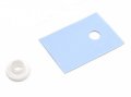
If the power transistors are not insulated, then you need the proper mounting hardware (nuts, bolts, insulators). If the transistor has a metal tab (collector), then you need a special insulating washer to fit over the bolt. By "ceramic" I think you mean "mica". Nowadays, flexible silicone pads are used. Always do a resistance check to make sure all of the leads are isolated from the heat sink.

1788363400794.png

What do you mean by "same IC501/502"? If the amplifier is running fine, leave it alone.
You can do the bias and current adjustments as recommended in the Service Manual.
 

Thread Starter

KaMel88

Joined May 11, 2026
59
It the amplifier is no longer blowing components or fuses and the transistors are running cool, you can remove the light bulb current limiter.

If the power transistors are not insulated, then you need the proper mounting hardware (nuts, bolts, insulators). If the transistor has a metal tab (collector), then you need a special insulating washer to fit over the bolt. By "ceramic" I think you mean "mica". Nowadays, flexible silicone pads are used. Always do a resistance check to make sure all of the leads are isolated from the heat sink.

1788363400794.png


What do you mean by "same IC501/502"? If the amplifier is running fine, leave it alone.
You can do the bias and current adjustments as recommended in the Service Manual.
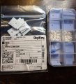
I have such sets, when I wrote ceramic I meant the white ones.

WhatsApp Image 2026-09-02 at 18.06.30.jpeg


Regarding IC501/502 left channel contains the original IC and the right channel contains a replacement. Should there be two identical ones, or does it not matter?
 
Top