[REQ] Small PSU with output 12VDC, 9VDC, 5VDC and 9VAC

Thread Starter

arjanv

Joined Oct 21, 2018
7
Hi,

This is my first post here, so if i'm doing something wrong....excuses.

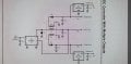
For a project the circuit needs these voltages on board 12VDC/1A, 9VDC/1A, 5VDC/1,5A and 9VAC/1A
Now the idea is to use a commonly available main adapter (5VDC or 12VDC) as input source.

Now my question, can someone help me creating this schematic for me. I can also pay for it.

Let me know.

Thanks in advance.
 

BR-549

Joined Sep 22, 2013
4,928
Is line voltage always available? 50 or 60 Hz? Are all voltage supplies..... supplying full current at same time?

Does the 9 vac load require a sine? Is size and weight a concern? How bout time and money?

Off the shelf components will do the task.
 
Last edited:

Thread Starter

arjanv

Joined Oct 21, 2018
7
thanks, i'm not good at all with power circuits.

Anyone can make a drawing for me? or help me with the values.

Did something myself but don't know if it is the way to do it like this.

and then how to create 9VAC?

thanks
 

Attachments

Thread Starter

arjanv

Joined Oct 21, 2018
7
Is line voltage always available? 50 or 60 Hz? Are all voltage supplies..... supplying full current at same time?

Does the 9 vac load require a sine? Is size and weight a concern? How bout time and money?

Off the shelf components will do the task.
It's for a Commodore 64. Size is a concern, but i assume it can be a lot smaller than the original.
9VAC is needed for a chip TOD signal(time of day) but this siganl can be replaced by a TOD generator, but some peripherals also needs 9VAC.

Thanks
 

BR-549

Joined Sep 22, 2013
4,928
Power Supply of the Commodore 64
The Commodore 64 is supplied by an external power supply unit via the power supply connector. It needs 5V DC voltage and 9V AC voltage. The 5V DC voltage should fluctuacte in a range of 4.95 to 5.10 Volt, else the C64 will not work properly. The power supply normally produces a voltage slightly higher than 5V, because of a small resistor between the voltage regulator and ground in the power supply.

C64 power supplies were made by at least three manufacturers. European Commodore 64s were typically accompanied with a power supply manufactured by a company called Ismet Tranformatoren. Ismet still exists today and manufactures high end transformers. C64s manufactured in the far east (especially C64C) were usually accompanied with power supplies by Dee Van, a Taiwanese manufacturer that also still exists today, and still manufactures power supplies for consumer electronics. The manufacturer(s) of the power supplies American C64s is not known to this Wiki.


  • C64 power supply by Ismet


  • Rear view of the Ismet PSU


  • A later C64 power supply by Ismet


  • C64 power supply by Dee Van
Owners of a C64 using an original power supply should regularly (for example, once a year) check the 5V DC function of their power supplies, as they tend to produce higher voltages as they wear out. Because the C64 almost directly uses the 5V to power its chips, higher voltages can become dangerous for the Commodore 64. If you measure the voltage of your power supply, you should interpret this as follows:

4.95 - 5.1V Power supply functions normally
5.1 - 5.2V Minor concern, measure the power supply more often
5.2 - 5.5V The power supply is failing. You Commodore 64 will not die right away, but it is an unhealthy situation. Replacement or repair of the power supply is recommended.
5.5 - 6V Your Commodore 64 is in danger.
>6V In most situations where a Commodore 64 got killed by its power supply, the voltage had risen above 6V. Usually the RAM memory gets damaged first.
The 9V AC line seldomly breaks in the original power supplies and the power circuits of the C64 handle slight voltage differences.

Should you want to design your own power supply, it needs to conform to these specifications:

  • Galvanic separation between the 5V DC and 9V AC lines is recommended. For a power supply without galvanic separation between 5V DC and 9V AC, you must first study the power circuits of the C64 mainboard to avoid that undesired currents will flow between the 5V DC and 9V AC lines.
  • 9V AC is usually generated by a transformer. Transformers drop their voltages if they are loaded: The transformer produces more than 9V when the C64 is off, and less when the C64 is on. This is no problem, the power circuits in the C64 handle this properly.
  • However, the minimum possible AC voltage on which the C64 will work correctly is about 8.1V AC. Make sure the voltage stays within safe margin from this, and test this with a datasette (which draws additional power from the 9V)
  • The AC voltage while the C64 is on should also not be much higher than 9V, as excess voltage is converted into heat, of which you don't want to produce too much. Therefore, do not use a too heavy transformer.
  • Respecting this, you will generally find that you need a transformer with a rating in the range of 10-15 VA, even though the C64 only draws approximately 5VA from the 9V line when in normal operation.
  • The original power supplies can deliver, depending on type, 1.5-1.7A. For the 5V lines, more is better, especially because modern cartridges, such as the 1541 Ultimate, increase the power consumption of the C64.
  • Recommended is to go for at least 2A on the 5V line. However, with modern switching power supplies, it is usually economic to go for 4A or 5A, which is perfectly fine, allthough the C64 will never draw that much power. It is pointless to make even heavier power supplies.
The above guidelines are based on the needs of C64 mainboards with NMOS chipsets. C64 mainboards with HMOS chipsets (usually C64C) draw less power, but since a power supply needs to be able to power both types of mainboards, these are the guidelines to aim for.

https://www.c64-wiki.com/wiki/Power_Supply

https://www.c64psu.com/c64psu/43-157-commodore-64-c64-psu-power-supply.html#/37-ac_plug_standard-eu


Last edited:

Thread Starter

arjanv

Joined Oct 21, 2018
7
Yes, i'm building a new c64 mainboard, but my idea was not to use the original Psu, but use a more available 5v or 12v adapter.
And the power circuit on the mainboard could be smaller.
 

geekoftheweek

Joined Oct 6, 2013
1,201
What about a couple wall warts mounted up inside a project box with a toggle switch to turn the main on and off? A 9 volt AC one should not be too hard to find and a 5 volt DC one you probably already have laying around. It won't be spectacular, but it will get the job done.
 
Top