 Facebook
 Google
 GitHub
 Linkedin
Hello,
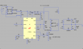
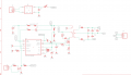
I designed a Multi-Winding/Multi-Output Flyback to generate +40V and -225V. In my application, the outputs need to work in a flip-flop load, where only one output handles a variable load of 0 to 50W at a time, while the other remains lightly loaded (just for stability). I used the LT8316 with no-opto (PSR) feedback, as shown in the attached file (some components are equivalent).
For the transformer, I used the TDK B66229G1000X187, with approximate inductances shown in the attached LTspice circuit. The winding specifications are:
I measured the leakage inductance at 13uH by shorting all the secondaries, including aux. This will make the K=0.98 (317/(317+6.5)).
Problem: In simulation with K=0.98, the outputs regulate well under any load. However, in the real circuit, the +40V rail drops to about +5V with even a 10W load, while the -225V rail performs well up to 45W.
As a test, removing the rectifier diode from the +40v rail resulted in a decent -225V across various loads, but by removing the rectifier diode from the -225v rail, the +40V rail still dropped to +5V even under light load (1w).
In summary, the +40V rail has poor load regulation, while the -225V rail performs well. How this is possible and how to resolve? If the design is bad, how come -225v is performing well?
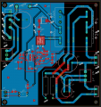
I've also attached my Schematic and PCB layout, which may not be ideal; however, even shortening paths (e.g., from aux to feedback resistor) has not improved performance.
I designed a Multi-Winding/Multi-Output Flyback to generate +40V and -225V. In my application, the outputs need to work in a flip-flop load, where only one output handles a variable load of 0 to 50W at a time, while the other remains lightly loaded (just for stability). I used the LT8316 with no-opto (PSR) feedback, as shown in the attached file (some components are equivalent).
For the transformer, I used the TDK B66229G1000X187, with approximate inductances shown in the attached LTspice circuit. The winding specifications are:
- Primary: 46 turns of AWG 22 (bottom layer)
- Aux: 7 turns of AWG 28
- Sec (+40V): 12 turns of AWG 22
- Sec (-225V): 68 turns of AWG 22 (top layer)
I measured the leakage inductance at 13uH by shorting all the secondaries, including aux. This will make the K=0.98 (317/(317+6.5)).
Problem: In simulation with K=0.98, the outputs regulate well under any load. However, in the real circuit, the +40V rail drops to about +5V with even a 10W load, while the -225V rail performs well up to 45W.
As a test, removing the rectifier diode from the +40v rail resulted in a decent -225V across various loads, but by removing the rectifier diode from the -225v rail, the +40V rail still dropped to +5V even under light load (1w).
In summary, the +40V rail has poor load regulation, while the -225V rail performs well. How this is possible and how to resolve? If the design is bad, how come -225v is performing well?
I've also attached my Schematic and PCB layout, which may not be ideal; however, even shortening paths (e.g., from aux to feedback resistor) has not improved performance.
Attachments
-
 125.1 KB Views: 9
 -
 83.6 KB Views: 9
 -
 43.8 KB Views: 7


