It was a nasty smell I meant. The battery was fine(well it didn't charge much) before the rectifier gave up it's . Well luckily a friend donated me an old Se rectifier he had and it's back working.
The old Selenium rectifiers are not very efficient. The new bridge rectifier is the reason you are getting a higher voltage. Probably a little high a voltage. Be great to get a flat battery charged up quicker, you would just have to keep an eye on the voltage & turn it of when it starts to get near 15V.
most basic chargers with iron core transformer will ruin the battery eventually - a more efficient rectifier will just get the job done quicker.
So called "smart" chargers are quite reasonable from discount stores - all my old "iron cored" chargers have been rigged with modest capacitance voltage doubling rectifiers for first line of defence sulphated battery recovery.
most basic chargers with iron core transformer will ruin the battery eventually - a more efficient rectifier will just get the job done quicker.
So called "smart" chargers are quite reasonable from discount stores - all my old "iron cored" chargers have been rigged with modest capacitance voltage doubling rectifiers for first line of defence sulphated battery recovery.
Smart chargers are the best for batteries as they substantially increase it's life. Unfortunately for me the battery voltage was way below for the smart charger to charge, which is when Lucas was called in! Looks like sometimes the dumber ones are good at the worst situations. xD
Smart chargers are the best for batteries as they substantially increase it's life. Unfortunately for me the battery voltage was way below for the smart charger to charge, which is when Lucas was called in! Looks like sometimes the dumber ones are good at the worst situations. xD
All the acid in a dead flat lead acid battery is hiding in the plates - if it actually left 100% pure distilled water behind; it would be an insulator.................
All the acid in a dead flat lead acid battery is hiding in the plates - if it actually left 100% pure distilled water behind; it would be an insulator.................
Yes I agree with you. But 100% distilled water means a fully sulfated cell right?
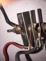
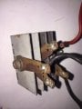
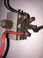
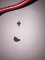
Also, I checked the rectifier. Tried measuring the voltage across the AC and DC terminals. DC on multi-meter diode test gave me 502. AC gave me 0 sice one of the layers in the 4 plates have the layer of coating on in burned off at one spot and its peeling off. I've attached pics off the rectifier plates- there is a grey coating on one side of the plates .I'm still not sure if its a copper oxide/selenium rectifier still.
Pic 1 shows the peeled of burned layer.
Pic 3 shows the burned mark.
Yes I agree with you. But 100% distilled water means a fully sulfated cell right?
Also, I checked the rectifier. Tried measuring the voltage across the AC and DC terminals. DC on multi-meter diode test gave me 502. AC gave me 0 sice one of the layers in the 4 plates have the layer of coating on in burned off at one spot and its peeling off. I've attached pics off the rectifier plates- there is a grey coating on one side of the plates .I'm still not sure if its a copper oxide/selenium rectifier still.View attachment 133152View attachment 133153View attachment 133154View attachment 133155
Pic 1 shows the peeled of burned layer.
Pic 3 shows the burned mark.
If the voltage is a little high with a silicon bridge rectifier then just add another diode in series with the positive (+) terminal and that should drop the voltage enough.
Yes a bulb in series would drop the current and limit it. You can choose a bulb that allows enough current.
Many selenium rectifiers actually had a series resistor added in the rectifier circuit to limit current.
Voltage drop 1v or less per section, each section could handle maybe 25 volts max, so they are stacked for higher voltages. At 12v i would think only one section is needed, but maybe 2. If there are more then maybe they wanted more of a voltage drop. Watch peak voltage too when charging.
Wow, last time i saw one of these was probably 40 or more years ago. Pulled out of old tube stuff like amps and radios and such. Wouldnt mind having one now to play around with, but last one i had was way way back then and i dont think i kept any of them although i might have one laying around somewhere, if it still works i dont know anyway. I do have some very old parts just kept for the novelty of it like very old transistors and diodes but they are small and easy to store.
The coating is paint - usually an odd grey/green colour. some manufacturers realised that matt black radiates heat better, a few like to show off with red or orange.
If the voltage is a little high with a silicon bridge rectifier then just add another diode in series with the positive (+) terminal and that should drop the voltage enough.
Yes a bulb in series would drop the current and limit it. You can choose a bulb that allows enough current.
Actually; you drop voltage as a product of current. Which a PTC bulb filament doesn't limit all that well.
At some point during charging, charge current starts to recover and the battery terminal voltage is low enough for the difference to light the bulb. unless you're using an "atom bomb to kill an ants nest" charger - all that does is take longer to do the bulk charge.
charge current ebbs as the battery terminal voltage comes up and a series bulb filament cools - when you can no longer see any glow, its resistance is not much higher than a piece of wire.
Actually; you drop voltage as a product of current. Which a PTC bulb filament doesn't limit all that well.
At some point during charging, charge current starts to recover and the battery terminal voltage is low enough for the difference to light the bulb. unless you're using an "atom bomb to kill an ants nest" charger - all that does is take longer to do the bulk charge.
charge current ebbs as the battery terminal voltage comes up and a series bulb filament cools - when you can no longer see any glow, its resistance is not much higher than a piece of wire.
You've never used a bulb to limit current? I've done it lots of times, even once so i could limit the current into a CRT TV set so i could trouble shoot it without causing an over current input which blows the fuse.
Bulbs have a non linear resistance. If you try to draw too much current, the current goes up to the max of the bulb and that's it. So if we use a 12v 1 amp bulb and try to use it to limit current into a 12v circuit, if the circuit tries to draw more than 1 amp it cant and the bulb lights brightly, but the current is only 1 amp even with a short circuit. Of course the bulb power rating and voltage rating has to match the job.
You've never used a bulb to limit current? I've done it lots of times, even once so i could limit the current into a CRT TV set so i could trouble shoot it without causing an over current input which blows the fuse.
I've done it loads of times - then the penny dropped, its not the best way of doing it.
Bulbing a blown fuse into an old style SMPSU, the reservoir electrolytic charging surge counteracts the PTC, and an NTC inrush surge limiter helps as well - but its still not impossible to destroy all those shiny new components you just replaced.
In series with the charging lead for a lead acid battery - it serves no useful purpose whatsoever.
I've done it loads of times - then the penny dropped, its not the best way of doing it.
Bulbing a blown fuse into an old style SMPSU, the reservoir electrolytic charging surge counteracts the PTC, and an NTC inrush surge limiter helps as well - but its still not impossible to destroy all those shiny new components you just replaced.
In series with the charging lead for a lead acid battery - it serves no useful purpose whatsoever.
Your first sentence, maybe i could agree for some applications but not for others. For others it seems like a good idea. You get low resistance to start with so if there is no problem it runs normally, but if the current goes too high then the bulb limits more and more. Seems good to me, at least sometimes.
In series with the charging lead for a battery i cant see a better way than using a bulb as long as the bulb type is chosen accordingly.
For example, a bulb might have 10 ohms cold and 100 ohms hot at 2 amps. Now connect this in series with a 14v source to charge a 12v battery. At only 2v the bulb should stay cool if it is the right type, and that allows about 200ma through. However, if the battery is shorted, the current is 14/100 which is 140ma.
If one cell is shorted we might see 4v across the bulb so the resistance will be maybe 20 ohms, and 4/20 is 200ma. So we seem to have some decent current limiting, but as the battery gets up near 12v we still have a decent charge current.
Now if we use a resistor, to limit to 200ma at 12v we'd need a 60 ohm resistor. To limit at 14v we'd need a 70 ohm resistor. With a shorted battery we get 200ma, but as the battery comes up to near 12v we'd see 2/70 amps which is 28.6ma which is hardly any charge current at all.
So the non linear character of the bulb seems to work out nicely, but again we have to choose the bulb to fit the application. Not just any bulb we have laying around. Granted this may not always be possible because we might not have the correct bulb laying around.
And yes, there will be a 'surge' current during start up. But that surge current is a function of the bulb we choose, and if we choose it right it should be ok.
Maybe there is a better choice, such as a resistor in parallel or in series with a bulb, but we could investigate all these scenarios.
Another benefit of a bulb is the power handling ability. It can handle the power it was rated for. Trying to get a 100 watt resistor for example can be much more expensive. Cheap bulbs can handle the power.
Your first sentence, maybe i could agree for some applications but not for others. For others it seems like a good idea. You get low resistance to start with so if there is no problem it runs normally, but if the current goes too high then the bulb limits more and more. Seems good to me, at least sometimes.
The inrush current from a bulb filament is an excellent way of testing whether all those shiny new components are going to go bang at switch on.
for lead acid charging - the current falls along the way and the filament is eventually cool enough for the PTC characteristic leaves you with pretty much just a bit of wire, a resistor is better - but still not good enough.
Listen or don't listen - you're paying for the gear you wreck.
The inrush current from a bulb filament is an excellent way of testing whether all those shiny new components are going to go bang at switch on.
for lead acid charging - the current falls along the way and the filament is eventually cool enough for the PTC characteristic leaves you with pretty much just a bit of wire, a resistor is better - but still not good enough.
Listen or don't listen - you're paying for the gear you wreck.
You seem to be talking to the wind. I already told you i had success with thsi kind of testing under the right conditions. BTW when i tested that TV i talked about i had no other way to limit the current for the test because i didnt have a variac back then and no power resistors that could handle the possible current.
So it appears you are the one not listening, or at least not reading my replies. Try reading my reply next time before posting a reply yourself and trying to understand what is being said.
One of the biggest points i can make here is about that one TV set. I did not have all my test equipment with me so i was very limited in what i could use for the test. I had no variac, and i had no power resistors that could handle the power needed for the current limiting. The light bulb worked out just fine. I was able to find a bad rectifier in the main bridge circuit (CRT TV). Once replaced, the TV worked again for maybe 3 years.
Now if i had a variac i would have probably used that first, but i did not have that on hand at the time.

 Facebook
 Google
 GitHub
 Linkedin