Replacing part of the board with re-etched PCB board

Thread Starter

greatwhite

Joined Dec 22, 2014
19
Hello,
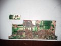
I have this mess (see image below)
20141226_141341.jpg
Where the leads are going to the 20pin are pretty bad. My plan is to take a brand new piece of copper plated board, re-etch the leads.

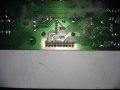
Cut the messed up part of the board (see example image below it is not the board I'm working just example)
Then re-attach the newly etched part to where it belongs on the board.
So can anyone tell me the do's and don'ts of this project please. Or any helpful techniques that will make this a success? I await any and all your replies and thank you.
 

Attachments

Last edited:

jpanhalt

Joined Jan 18, 2008
11,087
There will be a lot of jumper connections (i.e., from the new board to the existing traces). I am assuming it is a single sided board. If it is double sided, this suggestion won't work. I would consider having a double-sided board made with a reasonably exact copy of what you want on both sides. The TH plated contacts let someone else do the hard part. Then tin each trace on the damaged board and hot air or hand solder the repair board on top of the existing board. It will float down into place. That will give you both mechanical strength and a decent looking circuit. In other words, it is a bit like soldering a BGA device or device in which the contacts are folded under the device on top of the existing board.

John
 

Thread Starter

greatwhite

Joined Dec 22, 2014
19
There will be a lot of jumper connections (i.e., from the new board to the existing traces). I am assuming it is a single sided board. If it is double sided, this suggestion won't work. I would consider having a double-sided board made with a reasonably exact copy of what you want on both sides. The TH plated contacts let someone else do the hard part. Then tin each trace on the damaged board and hot air or hand solder the repair board on top of the existing board. It will float down into place. That will give you both mechanical strength and a decent looking circuit. In other words, it is a bit like soldering a BGA device or device in which the contacts are folded under the device on top of the existing board.

John
 

Thread Starter

greatwhite

Joined Dec 22, 2014
19
Wow!
Thank you jpanhalt very clever indeed. I would've never thought to do what you mentioned at the end of your response with folding the leads around and simply placing on top of the existing area.
 

Thread Starter

greatwhite

Joined Dec 22, 2014
19
I'm sorry my friend, but this looks like a board ready for the trash. I suggest you start over, from the beginning. What did you do the modifications with, a belt sander?
No that's how the board looked like when I bought the item off Amazon. It didn't power up when plugged it in si I got a full refund plus I was allowed to keep the unit.
 

Thread Starter

greatwhite

Joined Dec 22, 2014
19
There will be a lot of jumper connections (i.e., from the new board to the existing traces). I am assuming it is a single sided board. If it is double sided, this suggestion won't work. I would consider having a double-sided board made with a reasonably exact copy of what you want on both sides. The TH plated contacts let someone else do the hard part. Then tin each trace on the damaged board and hot air or hand solder the repair board on top of the existing board. It will float down into place. That will give you both mechanical strength and a decent looking circuit. In other words, it is a bit like soldering a BGA device or device in which the contacts are folded under the device on top of the existing board.

John
Yes it is a single sided board and I have the 20pcs of jumper connections ready to go.
 

jpanhalt

Joined Jan 18, 2008
11,087
You could also do it with a homemade, single-sided board (using fine wire for the TH connection), but unless you are really into DIY PCB making, I wouldn't recommend it.

John
 

Thread Starter

greatwhite

Joined Dec 22, 2014
19
I'm sorry my friend, but this looks like a board ready for the trash. I suggest you start over, from the beginning. What did you do the modifications with, a belt sander?
No I bought a Numark DXM09 DJ Mixer off Amazon. When it arrived I plugged it in and the unit wouldn't power up. So I got a full refund from the seller and the seller let me keep the unit as well. So I opened it up and that's how that part of the board already looked like. Sure enough the 20pc pin connector that attaches to this part of the board is connected at the other end to where else the sub assembly board below that sends power and audio in/out to the main board that has the messed up 20pin area on the board. Ergo unit not powering up and all I'm looking to do is cut the mess out and then from the still intact leads on the original board have jumper connections from there attach to the newly created/etched pcb board to allow for the 20pin connector piece to actually connect.
 

Alec_t

Joined Sep 17, 2013
15,156
Personally, I'd just use tinned copper wire jumpers between the trace remnants and the pins, always assuming I could be sure which trace went to which pin (some potential links appear ambiguous).
 

Thread Starter

greatwhite

Joined Dec 22, 2014
19
You could also do it with a homemade, single-sided board (using fine wire for the TH connection), but unless you are really into DIY PCB making, I wouldn't recommend it.

John
I'm totally into making my own PCB boards and that's exactly what I'm trying to do here. I gather I'm going to have to do a bit of both. Meaning creating a new section of board to allow the 20pin connector to actually connect to this part of the board and use jumper connections from the original part of the board having them connect to the new part of the board...am I correct in what I'm saying?
 

Thread Starter

greatwhite

Joined Dec 22, 2014
19
Personally, I'd just use tinned copper wire jumpers between the trace remnants and the pins, always assuming I could be sure which trace went to which pin (some potential links appear ambiguous).
Thank you Sir, I thought of that and I do know where each trace lead connects to each of the 20 pins. I just thought it would be really difficult working with fine wire and super limited space between each lead that if I sneezed or breathed the wrong way it I would make a mistake.
 

#12

Joined Nov 30, 2010
18,224
I could do that by stripping the enamel off some 30 ga wire and soldering it in. Finish up with Krylon Clear to keep anything from moving, but it's called, "work" for a reason!
 

Thread Starter

greatwhite

Joined Dec 22, 2014
19
Personally, I'd just use tinned copper wire jumpers between the trace remnants and the pins, always assuming I could be sure which trace went to which pin (some potential links appear ambiguous).
Ah ha...so you mean to already have the 20pin straight pcb mount on the board with all 20 straight pieces sticking through the other side, then run copper wire from the good part of the trace leads wrapping each one according to the pin they're assigned to?
 

Thread Starter

greatwhite

Joined Dec 22, 2014
19
I could do that by stripping the enamel off some 30 ga wire and soldering it in. Finish up with Krylon Clear to keep anything from moving, but it's called, "work" for a reason!

I'm not at all afraid of work believe you me I'm all about efficiency for the max amount of production in least amount of steps. If at the end of this storyboarding period and suggestions I'm receiving, I decide to go your route then that's exactly the work I need to do. and thank you.
 

killivolt

Joined Jan 10, 2010
836
You should see some of the air mounted repairs we did on Sears TVs in the 1970's. :eek:
Getting a replacement board was almost impossible because, "Circuit boards don't go bad".
They do when there is a hole burned clear through them! :D
I'd be interested in who built them; Magnavox, GE, or Zenith?

kv

Edit: Have no idea, my time at sears their was only one TV guy. He was really not open to questions. I think he had no idea what he was doing.
 
Last edited:
Top