
In the basic version of the emitter follower, if the emitter resistor is replaced by capacitive impedance or inductive impedance, what changes do we observe? Does the transistor no longer remain in active region?
Replacing emitter resistor by frequency dependent impedance in emitter follower circuit
- Thread starter Electron2002
- Start date
-
- Tags
- emitter-follower
Scroll to continue with content
The region where the transistor can operate is defined by the DC current Ic and the DC voltage Vce. So you can find the answer by yourself - how will these parameters change when the resistor Re is replaced by a capacitor or an inductor.
I'm new to electronics, so I face difficulty in figuring out certain things. It would be very helpful if you would point out the differences in DC analysis in this case, or the AC analysis. I've simulated the circuit and it shows that Ic=beta Ib holds for an inductor, but not for the capacitor.The region where the transistor can operate is defined by the DC current Ic and the DC voltage Vce. So you can find the answer by yourself - how will these parameters change when the resistor Re is replaced by a capacitor or an inductor.
I was talking about replacing the emitter resistor with the capacitor or inductor, not adding in parallel or series. In that case it would be unaffected, I realise, for the capacitor. But, when I replace the emitter resistor by a capacitor, it should be an open circuit after some time after the capacitor is charged. Does that affect the DC bias? This does not happen for the inductor, if it replaces the emitter resistor, right?Typically the capacitor would be added in parallel with the emitter resistor, and the inductor would be added in series with the emitter resistor, so that the DC bias is not affected.
Audioguru again
- Joined Oct 21, 2019
- 6,690
The transistor will not work if its emitter resistor is replaced with a capacitor.
Yeah, I realise that. If you could explain why, it would be really helpful.The transistor will not work if its emitter resistor is replaced with a capacitor.
Sounds like current-dumping
http://www.keith-snook.info/wireles...d-1975/Current Dumping Audio Amplifer DCD.pdf
http://www.keith-snook.info/wireles...d-1975/Current Dumping Audio Amplifer DCD.pdf
dcbingaman
- Joined Jun 30, 2021
- 1,065
I can get a 'semi' working circuit out of it. See attached sim.
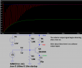
Of course the values of the caps play a major role on behavior. I did not experiment around with other values. It is highly non-linear. With no AC signal input the emitter cap charges to the base bias voltage and stops charging, thus no BE current the transistor is in the cutoff region and the output at the collector is the DC supply rail. But when an AC signal is coupled into the circuit via a cap the transistor can be forced out of cut off and actually perform some non-linear amplification as shown in the sim.
Of course the values of the caps play a major role on behavior. I did not experiment around with other values. It is highly non-linear. With no AC signal input the emitter cap charges to the base bias voltage and stops charging, thus no BE current the transistor is in the cutoff region and the output at the collector is the DC supply rail. But when an AC signal is coupled into the circuit via a cap the transistor can be forced out of cut off and actually perform some non-linear amplification as shown in the sim.
Attachments
-
1.2 KB Views: 9
Last edited:
Audioguru again
- Joined Oct 21, 2019
- 6,690
I lengthened the time duration of the simulation:
Attachments
-
 34.2 KB Views: 20
A capacitor blocks DC current so the transistor has no bias current.I realise that. If you could explain why
dcbingaman
- Joined Jun 30, 2021
- 1,065
Good catch. I should have tried for a longer duration. So even the AC stops working after short time. Makes sense. If the voltage goes up due to an AC input the emitter capacitor is going to charge to a higher voltage but it has no discharge path being that the BE acts like a diode there is no way for it to shed that extra voltage. If you drive it up high enough you could possibly damage the transistor by exceeding the BE max reverse bias voltage which is usually low for a BJT.I lengthened the time duration of the simulation:
dcbingaman
- Joined Jun 30, 2021
- 1,065
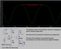
Here is another one. Where naturally I added a emitter resistor in parallel with the cap. It 'works' if you want to call it that. This circuits relies to much on the unstable beta of a transistor.I lengthened the time duration of the simulation:
Attachments
-
1.3 KB Views: 2
@audio guru, good example showing dampening and distortion on the waveform by introducing capacitance on the emitter to ground of a single stage BJT amplifier. To add to that nice example with the intent to expand on that, the time duration after 5 iterations shows too much impedance causes the negative half of the sine to go pointed and loses symetry with the nicely shaped sine in the positive cycle and that can be seen as a bias problem.
Historically in early radio a dampening problem with 5 or less was not a good candidate for feedback or adjusting the couplng coefficient of the exciter primary coil.
In a second stage shaping of the waveform may be possible when there is enough waveform over a longer time duration the dampening is found. Scoping both emitter and collector of a single stage BJT amplifier does give some useful information about waveshape distortion and impedance.
@Ion, The discovery date of Negative feedback unknown probably B.C.E ,the triggering of water duct valve as the level dropped.
The Harold Black, negative feedback as in an electrical amplifier is a noteworthy contribution in telecommunications and is also an interesting story.
Harold when interviewed is amoung so many electrical scientist that cannot seem to explain the moment he calls the "flash of recognition"
This feedback increases bandwidth and improves input and output impedances. In negative feedback, the feedback energy (voltage or current), is out of phase with the input signal and thus opposes it. Negative feedback reduces gain of the amplifier. It also reduce distortion, noise and instability.
The lesser known benefits how that is done with op amps improve SNR
https://www.allaboutcircuits.com/te...rt-3-improving-noise-linearity-and-impedance/
Last edited:
dcbingaman
- Joined Jun 30, 2021
- 1,065
Finally here is a properly designed transistor amplifier with a nice fixed gain of -10 along with a reduction in impedance to 1K output. This circuit is much more stable and independent of the unstable beta of the transistor.I lengthened the time duration of the simulation:
Attachments
-
1.4 KB Views: 7
Audioguru again
- Joined Oct 21, 2019
- 6,690
I change the values of a few parts for maximum voltage gain, minimum phase shift and maximum output level without any clipping. The distortion is awful without any negative feedback.
Attachments
-
 29.7 KB Views: 12
Just a small, but important, correction: Negative feedback does not "reduce...instability".Negative feedback reduces gain of the amplifier. It also reduce distortion, noise and instability.
The lesser known benefits how that is done with op amps improve SNR
In contrast, negative feedback increases the tendency to instability (reduced phase margin).
But that is the price we have to pay for the other advatages mentioned by you.
Do you mean me? @Ion hasn’t been seen for 12 years!@Ion, The discovery date of Negative feedback unknown probably B.C.E ,the triggering of water duct valve as the level dropped.
The Harold Black, negative feedback as in an electrical amplifier is a noteworthy contribution in telecommunications and is also an interesting story.
Harold when interviewed is amoung so many electrical scientist that cannot seem to explain the moment he calls the "flash of recognition"
This feedback increases bandwidth and improves input and output impedances. In negative feedback, the feedback energy (voltage or current), is out of phase with the input signal and thus opposes it. Negative feedback reduces gain of the amplifier. It also reduce distortion, noise and instability.
The lesser known benefits how that is done with op amps improve SNR
https://www.allaboutcircuits.com/te...rt-3-improving-noise-linearity-and-impedance/
Negative feedback is really interesting, and I do know about Harold Black, but I don’t know why you are telling me.
Early examples of negative feedback are James Watt’s flyball Governor, and various mechanisms to turn windmills to face the wind and regulate their speed.
It is much older in biological systems - how do you think we regulate our body temperature to 37°C?
Walker’s current dumping amplifier is a very good example of using a frequency-dependent impedance in the output of an emitter follower, which is what this post was about.
Negative feedback doesn‘t improve stability, it reduces phase margin as @LvW pointed out, and, on its own, it adds to the noise by adding the noise of the feedback resistor. The example you quote reduces noise by adding extra gain, as well as adding feedback. without the extra gain it can’t reduce the noise. The high power noisy amplifier it uses as an example might also be slow, in which case closing the feedback loop around both it and the extra low-noise amplifier might be problematic.
If “Eureka moments” interest you, it’s something my wife studies - she was recently interviewed by National Geographic about Newton and the falling apple.
https://www.nationalgeographic.com/science/article/eureka-insight-newton-archimedes-genius-science
People's eureka and epiphany moments always intrigued me. They make for nice stories.Do you mean me? @Ion hasn’t been seen for 12 years!
Negative feedback is really interesting, and I do know about Harold Black, but I don’t know why you are telling me.
Early examples of negative feedback are James Watt’s flyball Governor, and various mechanisms to turn windmills to face the wind and regulate their speed.
It is much older in biological systems - how do you think we regulate our body temperature to 37°C?
Walker’s current dumping amplifier is a very good example of using a frequency-dependent impedance in the output of an emitter follower, which is what this post was about.
Negative feedback doesn‘t improve stability, it reduces phase margin as @LvW pointed out, and, on its own, it adds to the noise by adding the noise of the feedback resistor. The example you quote reduces noise by adding extra gain, as well as adding feedback. without the extra gain it can’t reduce the noise. The high power noisy amplifier it uses as an example might also be slow, in which case closing the feedback loop around both it and the extra low-noise amplifier might be problematic.
If “Eureka moments” interest you, it’s something my wife studies - she was recently interviewed by National Geographic about Newton and the falling apple.
https://www.nationalgeographic.com/science/article/eureka-insight-newton-archimedes-genius-science
Audioguru again
- Joined Oct 21, 2019
- 6,690
Why doesn't this website warn us that this thread is ancient?@Ion[/USER] hasn’t been seen for 12 years!


