Facebook
 Google
 GitHub
 Linkedin
I'm at a loss actually...
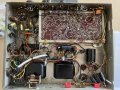
I bought this jukebox and amp "revised" but having recently bought a capacitor kit, and looking at what the amp looks like straight from 1958, I honestly have no clue what I'm doing.
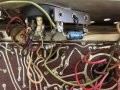
I can confirm so far that the fuses are not blown (the multimeter never says OL), but there is a part that concerns me and looks odd, as if the solder is crumbling. I've decided to go see a professional, although they already told me it's not quite their expertise.
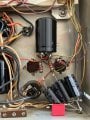
Besides that, the old selenium rectifier was already replaced with the small black one (not by me).
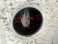
The two capacitors 73474 and 73475 are also disconnected, and were replaced with the big black one on the right.
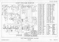
I've added the full schematics
I bought this jukebox and amp "revised" but having recently bought a capacitor kit, and looking at what the amp looks like straight from 1958, I honestly have no clue what I'm doing.
I can confirm so far that the fuses are not blown (the multimeter never says OL), but there is a part that concerns me and looks odd, as if the solder is crumbling. I've decided to go see a professional, although they already told me it's not quite their expertise.
Besides that, the old selenium rectifier was already replaced with the small black one (not by me).
The two capacitors 73474 and 73475 are also disconnected, and were replaced with the big black one on the right.
I've added the full schematics
Attachments
-
 1.4 MB Views: 16