Replacement for fusible resistor RWT05

Thread Starter

FOXD

Joined Feb 29, 2012
5
Hi,
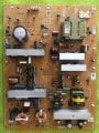
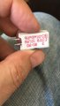
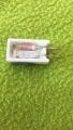
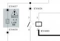
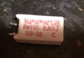
I have a broken Sony Bravia TV that has popped this fusible resistor RWT05 (Image from the schematic and the component PDF attached). It seems that it consists essentially of a thermal fuse (250v,2A,142C ) in series with a 6.8 ohm resistor. It is very hard to find a replacement..
My question is: is it possible to replace this with a thermal fuse in series with a normal resistor? If not, any ideas?
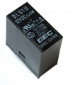
Apparently the cause for this blowing can be the relay (RY6000 shown in the schematic and picture attached). The relay can be switched manually but how can you check if its operating normally? This has the model DEC DLS1U 12VDC 0.25W.

Thanks in advance,

Todd
 

Attachments

DickCappels

Joined Aug 21, 2008
10,661
Yes, it is possible and would probably work, but I would go to a lot of trouble finding the correct replacement part before I took it upon myself to assume that the obvious substitute is as safe as the original solution. At the very least try to match the fusing characteristics of the original part.
 

Thread Starter

FOXD

Joined Feb 29, 2012
5
HI Dick,

I did find the right part but it seems you need to order minimum 1000 of them! Not really a solution for me unfortunately. I don"t know a lot about these fuses, and was wondering if the amp rating is that important or mostly the voltage/temperature rating? The reason being is I can only seem to easily find thermal fuses with a 10A rating (250v,10A,142C ) instead of the 2A rating of the original component.
 

DickCappels

Joined Aug 21, 2008
10,661
Mainly amperage, there is a different kind of fuse for thermal safety.

Congratulations on locating the part. It is too bad the appliance manufacturer doesn't make replacement parts available.

I found that I can get special replacement parts from a local appliannce repair shop.
 

Shimra01

Joined Nov 13, 2017
35
Hi I know this post is more than a year old but it helped me to solve my problem a few days ago. I found out which parts I needed to repair my TV. So I created my own Thermal resistor from low cost items. I bought the 5W ceramic resistor and the 145 degrees (centigrade) thermal fuse, (total cost $3). I then soldered the fuse to the resistor such that I could bend the fuse to the back of the resistor. Be careful when you solder the thermal fuse as its shorts at 145 degrees, so I used a water drenched sponge which I placed under the fuse to keep it cool and I cut and pre-soldered the wires. So the soldering time of the resistor to the fuse was as short as possible, keeping the fuse safe from shorting. Once I had the thermal fuse soldered I bend it to the back of the resistor and put a heat shrink tube over it, heated that at low heat such that it shrunk into one package. Then to solder this package into place on the PCB I again used the water drenched sponge to keep my fuse cool during soldering. After all this I tested my Powerboard and it worked like a charm. I am sorry I haven't made any pictures of the process so I could share. But I hope you can use your imagination in how to do it otherwise an ask me.I hope this is still useful to people as there are still many PCB's with these kind of resistor Thermal fuse combinations.
 

Rising73

Joined May 30, 2020
1
Hi I know this post is more than a year old but it helped me to solve my problem a few days ago. I found out which parts I needed to repair my TV. So I created my own Thermal resistor from low cost items. I bought the 5W ceramic resistor and the 145 degrees (centigrade) thermal fuse, (total cost $3). I then soldered the fuse to the resistor such that I could bend the fuse to the back of the resistor. Be careful when you solder the thermal fuse as its shorts at 145 degrees, so I used a water drenched sponge which I placed under the fuse to keep it cool and I cut and pre-soldered the wires. So the soldering time of the resistor to the fuse was as short as possible, keeping the fuse safe from shorting. Once I had the thermal fuse soldered I bend it to the back of the resistor and put a heat shrink tube over it, heated that at low heat such that it shrunk into one package. Then to solder this package into place on the PCB I again used the water drenched sponge to keep my fuse cool during soldering. After all this I tested my Powerboard and it worked like a charm. I am sorry I haven't made any pictures of the process so I could share. But I hope you can use your imagination in how to do it otherwise an ask me.I hope this is still useful to people as there are still many PCB's with these kind of resistor Thermal fuse combinations.
Hi I know two years passed but I have an experiment that I have to say. My Sony tv had the similar problem a few days ago and I sort this problem on the internet I watched some videos and read some articles and now today I solved the problem. First of all I measured the voltage in and out for the resistor RWT05 6.8ohm and I decided it’s broken. Then I disassemble the resistor then I scraped the cement and picked up the broken fuse then lengthen the resistor’s leg for soldering to the circuit. Now it’s working. Now I’m looking for the thermal fuse for 142 cantigrade Celcius. I’m going to buy it and replace with the wire that I have lengthen before. I take some photos to share with you. Bye...
 

Attachments

JdenHartog

Joined Jan 21, 2021
1
Hi,
I was able to buy a new WRT05 from AliExpress and used the "water drenched cloth method" mentioned above (thanks!) to cool the WRT05 while soldering. I also put the WRT05 in the freezer for some time, to start soldering with a cool fuse. My Sony Bravia KDL-40Z4500 is working flawlessly for weeks now!
 
Top