Replacement for a ATE 7CS 47R resistor

Thread Starter

Jonlate

Joined Dec 21, 2017
118
Hi guys,
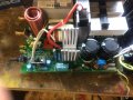
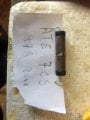
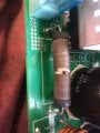
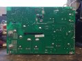
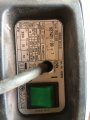
I have a welder that has blown the ATE 7CS 47R resistor.
From what I have found it has these parameters.....
Resistor TypeWire Resistor
Resistance47 Ohm
Tolerance (±)5 %
Power Rating10 W
Voltage Rating - DC685 V
Operating Temperature Min.-55 °C
Operating Temperature Max.350 °C
Body Diameter9.5 mm
Body Length35 mm
Temperature Coefficient±100 ppm/°C
Termination TypeAxial
Mounting TypeThread Mount

Looking around I can find many 10watt 47 ohm resistors, but finding out the voltage rating of these resistors is proving harder to do.
This is a list from Arrow electronic website, but none of these tell me the voltage, can anyone help?
Or can anyone direct to another resistor that can work?
It seems that the ATE ones are either not stocked or postage to Ireland is crazy expensive, that’s why i was looking at arrows site as postage is free to Ireland.
Hopefully someone knows of something that will work!

Thanks for the help.

ps if the category needs changing please do so.


https://www.arrow.com/en/categories...stance Value:47;In Stock:Yes;Power Rating:10;
 

MisterBill2

Joined Jan 23, 2018
18,167
It is not likely that the voltage across a resistor in a welder will be a large consideration, and so I would be far more concerned with the power rating. But there is a question of why the resistor failed, because they very seldom fail for "no reason." So did you make some mistake using the welder, which sometimes happens? Or is there some other problem that has been repaired all ready? It is good to know what lead to the resistor failing so that the cause can be corrected.
 

Tonyr1084

Joined Sep 24, 2015
7,852
Identifying the failed component for clarity would be appreciated. However, if it's that broken thing - - - that doesn't look like a 10 watt resistor. Nor does it look to be thread mounted.

And I'm with MisterBill2 on this one - what lead to the failure??? If it's physical damage then there should be no other concerns. But if something burned it up (which is how resistors meet their doom) then there are other issues that need to be diagnosed and corrected. It's hard to tell from here or from pictures exactly what went wrong. But if a 10 watt resistor is "Broken" (not burned up) then it shouldn't be hard to find another resistor of the same rating.

Resistors are rated in ohms and watts. Voltage is not a consideration except in the case of extreme high voltages. You're not working with anything extreme (in the thousands of volts that is).
 

MisterBill2

Joined Jan 23, 2018
18,167
If nothing else has obviously failed, and it was not some sort of operator error that cause the failure, then looking at a circuit diagram to see what components are in series with that resistor would help to spot the parts to check.
Otherwise a short circuited diode or capacitor would cause the problem, or a transistor that will not switch off. Looking at the picture I see two large capacitors that may be suspect, and two heatsinks with semiconductor devices that should be checked. When you install the replacement resistor it would be wise to leave the leads a bit longer so that the resistor is spaced a bit off the board, by about 1/8 inch. That will protect the board from heat.
If you are able to look at the underside of the PCB and see the traces, whatever devices the failed resistor is connected to would be suspects that should be checked.
 

MisterBill2

Joined Jan 23, 2018
18,167
I had not considered that the failure could have been caused by mechanical vibration. I have a fan that had a vibration failure of a resistor for that exact reason. So it might be that nothing else had failed, and it is OK to replace the resistor. Ceramic parts are quite brittle. That is a metal film resistor and so it also does serve as a fuse, and so it should be replaced by a metal film resistor. The voltage rating will not matter in this application. But the wattage and resistance do matter.
 

Tonyr1084

Joined Sep 24, 2015
7,852
Do we know what sort of voltage is at that part of the circuit? If it's 24VDC as is not uncommon among welders, then 24V ÷ 47Ω = 510mA. 510mA x 24V = 12.26W. Of course, that voltage is assumed. IF it's 12VDC then it's 255mA and 3.064W. Given that the spec is 10W, it's probably not 24V. 12V is not a common welding voltage (amperage is where the welder develops its power). I'd opt for something higher wattage. Knowing what voltage is at that resistor may shed some light. Also, some pictures of the back side could be useful.
 

MisterBill2

Joined Jan 23, 2018
18,167
Examining the circuit board traces it is clearly not part of the welding power flow and probably not an integral control part. So I am guessing that the resistor was working within it's ratings, and therefore a similar device will be close enough. Given the size and wattage it seems reasonable that a metal film resistor is the best choice for the application.
 

Tonyr1084

Joined Sep 24, 2015
7,852
That is a metal film resistor and so it also does serve as a fuse
First picture in post #6 kind of looks like a wire wound resistor. Hard to tell.
Resistor TypeWire Resistor
Resistance47 Ohm
Power Rating10 W
Mounting TypeThread Mount

Wire Resistor, 47Ω, 10W, Thread mount - - - Are we sure we have the right description of the part? That doesn't sound like a ceramic to me.
 

MisterBill2

Joined Jan 23, 2018
18,167
OK, I could be wrong, I can not resolve any wires in the photos and with the shine it sort of looked like metal film. Wirewound would be more common and easier to get, but if using a wirewound avoid getting a higher wattage rating, since it will need to act as a fuse. If the TS has a reasonable ohm meter it should be possible to measure the resistance from a lead to near the end of the broken section and get a fair idea as to what half of the actual value was. 47 ohms seems a bit low for that much wire, possibly 470 ohms?? An ohm meter check will give a good clue.
 

Thread Starter

Jonlate

Joined Dec 21, 2017
118
Hi guys,
To me the resistor looks like it has a ceramic core with wire wound around it.
The photo on post 6 shows what is written on the side of it.
The data came from ATE’s website as to what a 7CS was.

What would be the difference if I replaced it with a wire wound, film, or ceramic?
How would that affect The working of the welder?
Surely if they were all rated the same, wouldn’t they would all do the same job regardless what they were made of?

i will get the multimeter out and measure the two halves and see what I get as a total. That’s a good idea.

thanks again.
 

Tonyr1084

Joined Sep 24, 2015
7,852
If there's a designation on the PCB such as R22 (the number only indicates a part on a bill of materials), and if you can get the BOM then you will know for sure exactly what resistor you're talking about. The thing that stands out to me is the fact that according to the information you've provided it's a thread mounted resistor, which precludes axial lead components to a degree. I don't know and am not confident that you have the correct information on the resistor at hand. A resistor with numbers on it, depending on the tolerance, will be 470 meaning 47 ohms times 10 to the ZERO power, in other words, 47 ohms. 471 will be 47 ohms times 10 to the power of ONE, or 470 ohms. 474 would be 470,000 (notice four zeros). If you can discern numbers on the component then you should be able to tell its resistance. Size would indicate wattage; which is a second issue I have with that in the picture - it's too small to be a 10 watt resistor.

Whatever it is - for me - I need to be sure we're talking about the right component. To say the least, it IS a resistor and it APPEARS to be a wire wound resistor. Whether it's used as a fuse or not - that would depend on the engineering of the product. Still, it's always a good idea to go with the proper sized component. There have been RARE instances where I've gone with an over-rated component. Mother-in-law's washing machine had a fusible link rated at 102% of normal operation. I went with 146% rating. The 102% fusible link blew for no apparent or good reason. After the repair the unit has been running normal ever since. But it's rare to over-rate something. Capacitors can be safely over-rated (higher working voltage than the original) with no consequences. But with resistors, in the case of uncertainty as to exact functionality, it's good to go with an exact (or very close proximity) value and rating.
 

Thread Starter

Jonlate

Joined Dec 21, 2017
118
The number on the circuit board says it’s part R4, from a CFH 125 ISG welder.
Its definitely a through hole resistor as its soldered into place on the board. So what I thought was the Data information posted above may not be true.
The stamping on the resistor has 47R on it. So from what Tony is saying above, I need to find out if 47R means 4.7 ohms, 47ohms or even 470ohms!
And I need to do some more research as to the actual wattage of the part.
Finally I need to find out the voltage rating of the part. At the moment I think it needs to be 685v, but this could be wrong as well!
Back to google I suppose and try and find some out of circuit diagram for it, and what sort of resistor this is.
Why can’t life be simple at times!!
 

Attachments

MisterBill2

Joined Jan 23, 2018
18,167
The voltage rating means that it should not have voltages higher than that applied, which is very unlikely fot a 4.7 ohm resistor. The volyage rating is DP NOT EXCEED sort of specification, and just consider the current if you put evennten volts across the 4.7 ohms device. The voltage rating applies to ALL the devices in that style of package, including the 4.7 Megohm ones, where the voltage may be a lot higher.
 

Tonyr1084

Joined Sep 24, 2015
7,852
Resistors resist current. Current is the flow of electrons. Voltage is the pressure behind the current - it's what pushes the current through a device. Ohm's law shows that voltage, current and resistance are all inter-related. 10 volts and 10 ohms means there is 1 amp of current flowing through a device. Change it to 20 volts and now you have 2 amps flowing through the device. If you change the resistance to 5 ohms you now have 4 amps flowing through the device. Also directly related is wattage of the device. Resistors are also rated in wattage, which in ohms law is also directly related. Wattage is the amount of voltage (pressure) and current (the flow of electrons) multiplied. So 10 volts through a 10 ohm resistor will have 1 amp of current flowing through it and will be dissipating 10 watts of heat energy. 10 volts times 1 amp equals 10 watts. Imagine if you actually pushed 685 volts through that resistor. 685V ÷ 47Ω = 14.574 amps. 685V x 14.574A = 9983.5W(watts). That's a tremendous amount of heat energy. So even though your resistor may be rated at 685V, it wouldn't handle more than 10 watts before it burned up. And 10,000 watts is an order of several magnitudes higher.
 

MisterBill2

Joined Jan 23, 2018
18,167
Resistor operating voltage is a function of package size and type. It is not related to power dissipation. The most common issue with resistor voltage rating is in voltage dividers connected to high voltage circuits, such as voltmeters on high power RF amplifiers. Some designs used two 4.7 megohm resistors to monitor a 3000 volt supply, and the resistors failed because of excessive voltage across the package. So the resistor in this application has no challenge from the system voltage.
So please give the resistor voltage rating question a rest.
 
Top