Replace small motor in MG995 with larger motor

Thread Starter

Steven Middleton

Joined Feb 7, 2017
22
Hi guys,
I’ve got one for you. I’m trying to replace the small motor in an MG995 servo with a larger motor I pulled out of an 18v cordless drill. I’m trying to turn the cheap MG995 into a more powerful servo, without spending a lot of money on a more powerful servo.

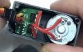
I figured out the mechanics and how I want to attach the pot to the end of the drill motor. The trouble I’m having is hooking the motor up to the circuit board inside the MG995.

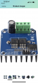
I thought I could use an H-Bridge, but that didn’t work, or maybe I hooked it up incorrectly. I will be controlling it with a raspberry pi. I just need help hooking up the H-Bridge between the drill motor and servo circuitry. Any help would be very appreciated at this point. Thanks in advance for your patience too.
 

AlbertHall

Joined Jun 4, 2014
12,346
Presumably you will also need a stronger gearbox as the drill motor will probably strip teeth in the original gearbox.

Essentially, you will be building a new servo from scratch.
 

Thread Starter

Steven Middleton

Joined Feb 7, 2017
22
Oh … I hope not. So hooking an h bridge or mosfet up for the motors extra power source won’t be the best solution?

Presumably you will also need a stronger gearbox as the drill motor will probably strip teeth in the original gearbox.

Essentially, you will be building a new servo from scratch.
[/QUOTE
 

BobTPH

Joined Jun 5, 2013
8,938
You don’t need the servo. The RPi can do what the servo would be doing. Just run the pot output into an analog input and write the code to position the motor based on the feedback.

Granted, this might not be that easy, depending on how precise you want it to be. But then, the servo was not tuned for the motor and gearbox you have, so it will probably not work anyway.

To get really good results, you likely would need a PID controller tuned to the actual hardware.
 

BobTPH

Joined Jun 5, 2013
8,938
I don’t know for sure if that would work or not, but my gut feel is that it will not. The servo controller is tuned for the speed of the motor, the inertia when starting and stopping, etc. These will be far different for your drill motor. What I would predict is that it would severely overshoot and the oscillate instead of achieving stable response. This is what a PID controller does when not properly tuned.

I wish someone else with more knowledge would weigh in.
 

Thread Starter

Steven Middleton

Joined Feb 7, 2017
22
I don’t know for sure if that would work or not, but my gut feel is that it will not. The servo controller is tuned for the speed of the motor, the inertia when starting and stopping, etc. These will be far different for your drill motor. What I would predict is that it would severely overshoot and the oscillate instead of achieving stable response. This is what a PID controller does when not properly tuned.

I wish someone else with more knowledge would weigh in.
I’m willing to try it and see what happens. Any thoughts on how to hook up the 18v battery to power the motor separate from the circuit so I don’t fry the circuit? I’m thinking H-Bridge or MOSFET because they have higher frequency switching than a relay.
 

Thread Starter

Steven Middleton

Joined Feb 7, 2017
22
Do you know what the output to the motor coming from the servo board looks like? That would be the first step.
I removed the motor and attached the red wires to the RPWM and LPWM pins on the H Bridge shown in the other picture. That basically made it turn in forward or reverse depending on the direction I moved the pot inside the servo but didn’t help with positioning.
I was controlling it with a simple servo tester.
 

Attachments

Top