Repairing 0-18VAC model railroad transformer

djsfantasi

Joined Apr 11, 2010
9,237
Some of the confusion is due to the fact that your statement:

Basically this unit just supplies a voltage onto the tracks.
…is demonstrably false. The Lionel ZW “transformer” does more than supply a voltage to the tracks. It provides control of things like lights, horn, direction… And possibly more (it’s been ~60 years since I used a ZW).

Plus, the ZW has four outputs, some variable and some fixed.

So some of us have this in mind, creating confusion.

There are others whose experience with model railroading control is limited to variable DC. Hence more confusion.

I wish I had the solution to a 0-18VAC supply controlled by a 10k potentiometer, since that appears to be all you want. But I wonder if what you want is what you need since so much is ill defined.
 

Thread Starter

Trainnut315

Joined Jul 11, 2023
12
Some of the confusion is due to the fact that your statement:


…is demonstrably false. The Lionel ZW “transformer” does more than supply a voltage to the tracks. It provides control of things like lights, horn, direction… And possibly more (it’s been ~60 years since I used a ZW).

Plus, the ZW has four outputs, some variable and some fixed.

So some of us have this in mind, creating confusion.

There are others whose experience with model railroading control is limited to variable DC. Hence more confusion.

I wish I had the solution to a 0-18VAC supply controlled by a 10k potentiometer, since that appears to be all you want. But I wonder if what you want is what you need since so much is ill defined.
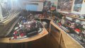
Well I've been using Lionel transformers for more than 70 years. I bought my first train in 1954, it still runs with original parts. Some units do have a fixed voltage output ,mainly for accessories. The ZW 's do not. All 4 outputs are variable and controlled separately by 1 of 4 handles. There are 2 models of ZW's ,1 has external power supply and 1 has an internal step down transformer. Both types do not control train direction , that is on board the engines via a device called an "E" unit. 1 type is mechanical, 1 is electronic. The main unit can ring the bell or horn but this is not necessary. On old style trains the speed is controlled by the output voltage. New style use onboard, the engines, electronics via a remotely held controller.
 

Ya’akov

Joined Jan 27, 2019
10,276
So, to get on track (I might have intended a pun, who knows?)...

First, I get that you just want a dimmer circuit for your voltage range, so this isn't about that. That's fine, and I am not going to question whether it will work or not, or if it is a good idea. I'm satisfied that you know what you want and it will be worth doing.

But, I would like to understand something, if you don't mind.

If you could repair the ZW so it did everything it originally did, would this be better in your eyes? The reason I ask is that while I am sure it is true that you can't program a new MCU (that 40-pin IC is almost certainly a microcontroller with Lionel's firmware on it) there are at least two possibilities that would make that moot.

First is that the MCU on the current board is just fine and the problem lies elsewhere (which, from my experience in general has a least a 50% chance of being true—that is, I don't have a reason to think it is any more likely to be dead than a coin toss).

Second is that one method for dealing with such a situation is to buy some other dead PCBs or ZWs and harvest parts that are good on that one and bad on yours. This is a very common practice when certain chips are unavailable or require programming that can't be done. And, an aside, it is very possible that if you could get ahold of a good one you could read the firmware and program others, depending on what it actually is and how they programmed it.

So, it may well be possible to restore the transformer to its former glory—if you want to.

I am also wondering why you are trying to make the ZW do this one thing. This is a real question. Do you just want the appearance of it, is the single control really special, or is it something else?

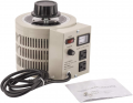
One way to get something working quickly is to buy an inexpensive variac also called an autotransformer. You could put in between the mains that the external power supply (ironically, the real transformer in this arrangement) and by adjusting the input to it get a varying output from 0-18V.

1689235088147.png

(Note that most variacs can provide more than the 120V input, so you would have to mark or mechanically block the knob to avoid overvoltage, but this is no big deal.)

Whatever you choose to do, I certainly wish you success with it. I am not a good source for dimmer circuits or I would provide some assistance. There are several members who are quite conversant in such circuits in particular and I hope they notice the thread.
 

BobTPH

Joined Jun 5, 2013
11,609
From the Lionel site:

The ZW-L can run up to four trains or accessories at the same time on different layouts. The two engineer-type handles provide independent control of two variable voltage circuits, each with built-in whistle, direction, and bell controls. Two additional accessory circuits can be set by means of the dial-type controls to any desired voltage.
This may be a new feature of the newer model, but it definitely says it controls direction on two of the circuits.
 

Thread Starter

Trainnut315

Joined Jul 11, 2023
12
From the Lionel site:


This may be a new feature of the newer model, but it definitely says it controls direction on two of the circuits.
Thanks for the reply but I think I'm in the wrong place to ask for help. ZW transformers have "4" handles, 2 big and 2 small. The output has 8 connections, 4 are electrically connected together and labelled common and are connected to the outside rails. [ This is a 3 rail system, centre rail is insulated from the outside rails. ]
The other 4 connections are 1 for each handle. Not electrically connected to each other. The transformer only turns the power on or off it doesn't control the direction unless the "E" unit is set to allow this .It does control the speed on the older systems by reducing/increasing the voltage. When running multiple engines, on a conventional system, it is set for one direction only. It does control the bell, horn or whistle but that is not needed. [FYI pressing the horn or bell puts a dc pulse on the output and a on board relay in the engine or a electronic part rings the bell or horn. On my trains there is an battery .in the engine, and a DC relay that supplies the power. Steam engines have the DC relay that when activated applies the AC voltage to the whistle motor.] Ed.WIN_20230203_15_55_35_Pro.jpg
 

nsaspook

Joined Aug 27, 2009
16,430
Seems to be a interesting hobby, that as usual, has created its own nomenclature that has diverged from its original roots. When I was a kid a 'rich' cousin had a train set that used this for the control.
1689263500534.png
there was a 'real' variable transformer inside. Obviously today the name and outer skin remains the same but the functionality and internal construction is different.
 

Thread Starter

Trainnut315

Joined Jul 11, 2023
12
Seems to be a interesting hobby, that as usual, has created its own nomenclature that has diverged from its original roots. When I was a kid a 'rich' cousin had a train set that used this for the control.
View attachment 298256
there was a 'real' variable transformer inside. Obviously today the name and outer skin remains the same but the functionality and internal construction is different.
Exactly what I'm using today. One I'm repairing is very different inside. Basically a regulated AC power supply.WIN_20230703_16_52_06_Pro.jpg
 

r.campari

Joined Jun 22, 2023
1
I'm trying to repair a Model Railroad transformer. I need a circuit that will use a 18 VAC input and have an output
from 0 to 18 vac using a 10 K pot. The input voltage and 10K pot CANNOT be changed. Only circuits I can find all have higher input voltage. Approx. 10 amps on output.
Thanks Ed
If you need a DC output you could think to use a siwtching power supply board easily found in ebay aliexpress ecc.
If you need an ac output like old marklin trains You could use a VARIAC transformer connected on primary side of 230/18 transformer
 

RPLaJeunesse

Joined Jul 29, 2018
264
If you aren't familiar with Lionel trains you shouldn't be responding to this forum. The original Lionel control scheme is pretty simple, basically a variable AC voltage. That can be done a ton of ways, from a simple variable transformer to a modulated full bridge PWM scheme that produces a true sine output (after filtering out the PWM carrier frequency). The bell and whistle get a bit more complicated as they introduce a DC offset into the signal presented to the rails, the specific amount of which I'm not familiar with. (Yes, I could unbox the train downstairs but I choose not to at the moment.) A secondary issue is power limiting, i.e. protecting the power source when something goes wrong and shorts out the track, typically a derailment consequence. Early Lionel electronic controllers were notorious for having poor self-protection with a shorted load, developing a competing product made a ton of money for a good friend who eventually exited the business. [The TMCC digital system is a different animal altogether with the AC on the tracks at full 18V, and control of the engine via a superimposed complex serial data stream FSK modulated in the 455 KHz region.]

So here's what the OP needs to do: start with a 10K pot and develop a (nearly) full range variable AC voltage derived from an 18V 10A feed. What should be done: detect an overload and latch the output off until something clears both the overload and the latch. What might need to be done: Provide a scheme to induce a DC shift in the output, at one polarity for bell and the other for whistle.

Just doing the first task is possibly a simple triac phase control, although the trivial R-C phase shift approach is probably inadequate to do the job. Think zero cross detector, synchronized ramp generator, PWM slicer, triac driver, triac. The overload task means a sense component (Lionel used 2.8" of some wire as the "10 Watt" sense resistor), likely some form of amplifier, a threshold detector, bistable latch, and a gate to be inserted between the aforementioned PWM slicer and triac driver. As for the task of inducing a DC shift in the output, that can be done by adding to the pulse width of positive (negative) half cycles and subtracting from the pulse width of negative (positive) half cycles. This can be done with analog electronics numerous ways, such as adding (subtracting) a synchronized powerline frequency square wave to the signal from the 10K pot.

Hopefully the reader and the OP now get a feel for the task(s) at hand and realize a simple triac phase controller circuit will not adequately do the job.
 

prepka

Joined Oct 5, 2020
34
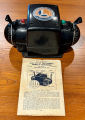
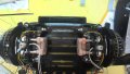
This is exactly what I'm repairing. The external parts are step down transformers. 110vac to 18 vac. They work fine. The main box, called a transformer by LIONEL, has a circuit board with 4 separate circuits on it. There are 4 inputs and 4 outputs. The PCB is burnt out. The output is only AC.. Depending on Engines used the output View attachment 298213View attachment 298214View attachment 298215View attachment 298216View attachment 298217View attachment 298213View attachment 298214View attachment 298215View attachment 298216View attachment 298217is either fixed on varied.
You are right about all four channels being the same, but I think that just replacing the power parts will not fix this. This is since the driver chips and circuits are likely smoked also. This looks like the new style ZW If we could get a close up of the board on both sides of the board then it may be able to create a schematic to understand how to repair this.
 
Top