Repairing 0-18VAC model railroad transformer

Ya’akov

Joined Jan 27, 2019
10,275
So would the trains work on DC, or just AC only?
as it's easier to make a variable DC power supply.
This whole thing is very complicated. Lionel uses AC with local rectifiers for the train’s DC motors, but there is a complicated scheme for controlling the trains.

Researching it is going down a rabbit hole, there is just not enough information in this thread to understand the problem.
 

Ya’akov

Joined Jan 27, 2019
10,275
It seems the op is trying to replace not repair.
That depends on what you mean by “repair”.

He’s presented his problem as making a circuit that will use a 10KΩ potentiometer vary a voltage (presumably with an 18VAC input) from 0-18V.

The voltage source and the potentiometers are part of an existing device that must be used. But that device is originally did far more that vary a voltage from 0-18V, and apparently the waveform might be critical to solving the real, unstated but referred to problem of repairing a Lionel ZW “transformer” by substituting a simple dimmer-type circuit for the complex control board in it.

So, replace? Yes, a part. But repair because the device has to do the job of powering and controlling the trains. He mentioned it “controls four trains”. It does this with control signals superimposed on the AC waveform. I can’t tell if the TS believes or knows that the device will work as he expects it to with a dimmer instead of the original PCB.

The problem is there is a whole bunch of mind reading going on, and the description of the problem is (potentially) very misleading resulting in a bunch or reasonable but possibly useless questioning by prospective helpers.
 

LowQCab

Joined Nov 6, 2012
5,101
If Lionel no longer sells or services this setup,
it's time to start with a "clean sheet of paper".

The requirements for the "Control-Scheme" have to be documented somewhere.

Until those requirements are found and made public, this project is going nowhere.
.
.
.
 

Ya’akov

Joined Jan 27, 2019
10,275
If Lionel no longer sells or services this setup,
it's time to start with a "clean sheet of paper".

The requirements for the "Control-Scheme" have to be documented somewhere.

Until those requirements are found and made public, this project is going nowhere.
.
.
.
The information is scattered around and it is not clear that anyone has done a thorough reverse engineering. While I can’t seay i have searched as I would for one of my own projects, I haven’t found anything that can be used to specify an alternative solution.

I suppose there is a chance the TS simply wants to run a single train, motor only, and the big “transformer“ is for show. But, he’d need to say so because it’s really not so obvious that’s what is intended at all.
 

MaxHeadRoom

Joined Jul 18, 2013
30,771
My OLD GE " Experimenters Manual" featuring SCR's and Triacs, show a Model RR controller. It features a Transformer followed by a Bridge rectifier followed by a simple transistor-SCR controlled circuit for the DC .
 

Ya’akov

Joined Jan 27, 2019
10,275
My OLD GE " Experimenters Manual" featuring SCR's and Triacs, show a Model RR controller. It features a Transformer followed by a Bridge rectifier followed by a simple transistor-SCR controlled circuit for the DC .
This isn’t DC. It’s a Lionel system where the locomotive models have a rectifier in them to power the DC motors, and control signals are imposed on the AC waveform. The controller can manage four trains on a common track. It seems there may be a multiphase thing going on as well.

There is something called TMCC. (Train Master Command and Control) which is a digital system that could be involved as well. In the end, unless this is a single, conventional train, 0-18V isn’t going to do what is needed.

Mind you it could be a single, conventional train—but he said it can “control four trains”, so…
 

Ya’akov

Joined Jan 27, 2019
10,275
So what you are saying is, the output of a transformer to full-wave bridge rectifier is NOT DC? :(
I am saying that the AC is connected to the track, the track is connected to the model through its bogies, the bogies are connected to a rectifier, and the rectifier is connected to the motor (for some value of “connected”, possibly through some control circuitry).
 

MaxHeadRoom

Joined Jul 18, 2013
30,771
I was referring to the GE design that is specifically aimed at at model RR control, (circa 1960/1970) it may have been a different system back then?
It uses pulse width control of the 120Hz DC ripple.
No AC after the bridge.
 

Alec_t

Joined Sep 17, 2013
15,149
Without a Variac, even getting a variable 0-18V AC from an input 18V AC, particularly at 10A (or is that 4 x 2.5A?), is going to be far from easy. On top of that there are the superimposed control signals required.
 

Ya’akov

Joined Jan 27, 2019
10,275
I was referring to the GE design that is specifically aimed at at model RR control, (circa 1960/1970) it may have been a different system back then?
It uses pulse width control of the 120Hz DC ripple.
No AC after the bridge.
Well, there was more than one, and this is the Lionel system in particular.
 

Ya’akov

Joined Jan 27, 2019
10,275
Without a Variac, even getting a variable 0-18V AC from an input 18V AC, particularly at 10A (or is that 4 x 2.5A?), is going to be far from easy. On top of that there are the superimposed control signals required.
It is 10A for each, the supply transformers which are out-board are 180W.
 

Thread Starter

Trainnut315

Joined Jul 11, 2023
12
That depends on what you mean by “repair”.

He’s presented his problem as making a circuit that will use a 10KΩ potentiometer vary a voltage (presumably with an 18VAC input) from 0-18V.

The voltage source and the potentiometers are part of an existing device that must be used. But that device is originally did far more that vary a voltage from 0-18V, and apparently the waveform might be critical to solving the real, unstated but referred to problem of repairing a Lionel ZW “transformer” by substituting a simple dimmer-type circuit for the complex control board in it.

So, replace? Yes, a part. But repair because the device has to do the job of powering and controlling the trains. He mentioned it “controls four trains”. It does this with control signals superimposed on the AC waveform. I can’t tell if the TS believes or knows that the device will work as he expects it to with a dimmer instead of the original PCB.

The problem is there is a whole bunch of mind reading going on, and the description of the problem is (potentially) very misleading resulting in a bunch or reasonable but possibly useless questioning by prospective helpers.
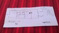
Thanks again all who replied. You are all making this far more complicated then it is.. Model train controllers have been called TRANSFORMERS since day one. The one I'm trying to repair could control conventional engines by varying the voltage, NO Electronics involved or control trains using systems like TMCC. With TMCC multiple trains,like 50 0r more can be controlled on the same track , that talk to the engines directly. The "transformer" only supplies the voltage required, usually +- 16 vac. There are 4 outputs but all are separate.WIN_20230712_12_30_32_Pro.jpgThis is what I'm looking for..
 

Dodgydave

Joined Jun 22, 2012
11,395
Thanks again all who replied. You are all making this far more complicated then it is.. Model train controllers have been called TRANSFORMERS since day one. The one I'm trying to repair could control conventional engines by varying the voltage, NO Electronics involved or control trains using systems like TMCC. With TMCC multiple trains,like 50 0r more can be controlled on the same track , that talk to the engines directly. The "transformer" only supplies the voltage required, usually +- 16 vac. There are 4 outputs but all are separate.View attachment 298202This is what I'm looking for..
That's the usual circuit for a dimmer, but the 47K between the two capacitors is normally a Diac (27V) to prevent the triac from firing instantly, you could try and use two 3V zener diodes back to back series to see if it works.
 

Ya’akov

Joined Jan 27, 2019
10,275
Thanks again all who replied. You are all making this far more complicated then it is.. Model train controllers have been called TRANSFORMERS since day one. The one I'm trying to repair could control conventional engines by varying the voltage, NO Electronics involved or control trains using systems like TMCC. With TMCC multiple trains,like 50 0r more can be controlled on the same track , that talk to the engines directly. The "transformer" only supplies the voltage required, usually +- 16 vac. There are 4 outputs but all are separate.View attachment 298202This is what I'm looking for..
Early on, I tried to explain that although the device you are working on is called a transformer among train hobbyists, it has a specific technical meaning in the electronics domain.

This is much more useful information than you originally provided.

Can I ask you a question: are you using the original housing and controls just for the look of it?

Also, you don‘t care about the horn and bell controls, correct?
 

djsfantasi

Joined Apr 11, 2010
9,237
I was referring to the GE design that is specifically aimed at at model RR control, (circa 1960/1970) it may have been a different system back then?
It uses pulse width control of the 120Hz DC ripple.
No AC after the bridge.
That would be ASTRAC and is unrelated to the proprietary Lionel control scheme.
 

Thread Starter

Trainnut315

Joined Jul 11, 2023
12
OK, folks—this is what we are dealing with…

It is a complicated controller that uses up to four supples (like the ones in front). Exactly which part the TS is trying to repair is not clear yet but I think it must be the ZW (the fancy phenolic controller bit).

A DESCRIPTION:


Unfortunately, all the information about it has been purged from Lionel’s website except that. I didn’t go spelunking to see if I could find more, but without more information from the TS I‘m afraid we are stumbling around in a huge problem space with the lights off and one leg tied behind our backs.
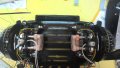
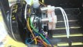
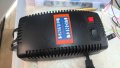
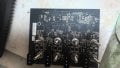
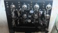
This is exactly what I'm repairing. The external parts are step down transformers. 110vac to 18 vac. They work fine. The main box, called a transformer by LIONEL, has a circuit board with 4 separate circuits on it. There are 4 inputs and 4 outputs. The PCB is burnt out. The output is only AC.. Depending on Engines used the output WIN_20230703_16_52_06_Pro.jpgWIN_20230703_16_52_34_Pro.jpgWIN_20230703_16_53_20_Pro.jpgWIN_20230703_16_53_39_Pro.jpgWIN_20230703_16_53_59_Pro.jpgWIN_20230703_16_52_06_Pro.jpgWIN_20230703_16_52_34_Pro.jpgWIN_20230703_16_53_20_Pro.jpgWIN_20230703_16_53_39_Pro.jpgWIN_20230703_16_53_59_Pro.jpgis either fixed on varied.
 

LowQCab

Joined Nov 6, 2012
5,101
It looks like You have 1 smoked Component,
which could be causing a Short-Circuit.
This could possibly affect the entire Board, or just one Output.

These Components are likely all identical.
If You can get a clear, close-up picture of one of the good ones
it may be possible to suggest a superior replacement-part.

A close-up picture of the burned-up area of the Board should show if additional
repair-work to the Board will be required.

I would suggest replacing all of these identical Components
at the same time with higher-rated new parts.
( they're cheap )
In addition to this, all of the Components which have a Metal-Tab should have
an appropriate Clip-On Heat-Sink added to them to prevent a similar future smoke release event.
( also cheap )
.
.
.
 

Thread Starter

Trainnut315

Joined Jul 11, 2023
12
It looks like You have 1 smoked Component,
which could be causing a Short-Circuit.
This could possibly affect the entire Board, or just one Output.

These Components are likely all identical.
If You can get a clear, close-up picture of one of the good ones
it may be possible to suggest a superior replacement-part.

A close-up picture of the burned-up area of the Board should show if additional
repair-work to the Board will be required.

I would suggest replacing all of these identical Components
at the same time with higher-rated new parts.
( they're cheap )
In addition to this, all of the Components which have a Metal-Tab should have
an appropriate Clip-On Heat-Sink added to them to prevent a similar future smoke release event.
( also cheap )
.
.
.
Thanks. I have done all of the above. When I started the unit had burnt out MOSFETS, which I replaced. I was told even if I got the PCB repaired there is a 40 pin IC chip that cannot be programmed as Lionel does not support this anymore. This project is very simple and I don't understand all the confusion. Basically this unit just supplies a voltage onto the tracks. Nothing fancy. Similar to a light dimmer switch. Appreciate your input.
 
Top