Remote activated electromagnetic coil - sanity check

Thread Starter

NickB

Joined Feb 1, 2016
95
Hi Guys

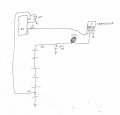
Someone gave me this circuit diagram a while ago and I’m just about to have a play with it but I was wondering if there may be a more efficient way to achieve the same result – perhaps one that uses less AAA batteries?

AAAs are used as the electronics are hidden in the base of the project and the height is restricted to approx. 15mm. The 50v cap is 2200uf and used for getting some more amps through the coil. The coil is activated via a quick, single press of a keyfob remote for a fraction of a second. The ‘jolt’ from the coil is used for moving objects that have neodymium magnets hidden in them.

The coil is approx. 5mm thick and 50mm in diameter with approx. 300 winds of 26SWG enamelled copper wire on a 8mm core.

I'm still a newb but keen to learn so any advice greatly appreciated.

Thanks
Nick
 

Attachments

Last edited:
seems an odd aproach all round...
why such a high voltage?
whats the transistor... A FET would probaqbly be a better choice. At the very least a darlington BJT.
How long is your pulse and why is there nothing controlling it?

Faking ghosts/spirits perhaps? What are you trying to move, how many times and how far?

What you have may work but it isnt pretty and is likely to be horribly inefficiant if the RX pulse is long or perminantly on.

You are going to need to add some detail to get a good answer...

Al
 

strantor

Joined Oct 3, 2010
6,875
You don't have a p/n for the transistor. TIP120 should work given the 1k base resistor. What you have drawn I would expect to work as long as you use off the shelf alkaline AAA batteries and not high dollar rechargeables, as the batteries will probably be the current limiting device . "Quick & dirty"
 

Thread Starter

NickB

Joined Feb 1, 2016
95
seems an odd aproach all round...
why such a high voltage?
whats the transistor... A FET would probaqbly be a better choice. At the very least a darlington BJT.
How long is your pulse and why is there nothing controlling it?

Faking ghosts/spirits perhaps? What are you trying to move, how many times and how far?

What you have may work but it isnt pretty and is likely to be horribly inefficiant if the RX pulse is long or perminantly on.

You are going to need to add some detail to get a good answer...

Al
Thanks for the reply. In answer to your questions:

My understanding is that increasing the voltage increases the current drawn and I need to get as many amps into the coil for a strong jolt. As mentioned in my original post, this is not my diagram, I'm just trying to get it to work/be more efficient. I need 6v minimum to power the RX.

FET is good and I have some N-channel ones I'll be trying.

Pulse from the RX is for as long as the button on the keyfob transmitter is pressed. A quick press is all I need. Circuit will have a reed switch somewhere so no drain when not in use.

Faking ghosts/spirits perhaps? Ha, hah. spot on! It's a wooden box similar in size to a shoe box. Coil is hidden in the lid and will knock objects over that are placed on the lid, eg, a wooden candlestick with a magnet in the base. It will be a single hit but needs to be a powerful jolt.

Any suggestions/improvememnts very welcome. Also, I'm not entirely sure what the cap before the + on the RX is for - flyback?

Many thanks
Nick
 

Thread Starter

NickB

Joined Feb 1, 2016
95
You don't have a p/n for the transistor. TIP120 should work given the 1k base resistor. What you have drawn I would expect to work as long as you use off the shelf alkaline AAA batteries and not high dollar rechargeables, as the batteries will probably be the current limiting device . "Quick & dirty"
Thanks for the reply. That's interesting as I was led to believe that rechargeable batteries provided more current than alkaline ones but slightly less voltage. As mentioned above I'll swap out the transistor for a FET.

Thanks
Nick
 

strantor

Joined Oct 3, 2010
6,875
Thanks for the reply. That's interesting as I was led to believe that rechargeable batteries provided more current than alkaline ones but slightly less voltage. As mentioned above I'll swap out the transistor for a FET.

Thanks
Nick
No you're right they do put out current, and I'm implying that could be a bad thing.
 
You might consider putting the, Well a large, capacitor in series with the coil and using the FET to discharge it through the coil.
Charge current would be limited by a resistor and each coil pulse would be the same as it would always be 1 capacitors worth of charge...

upload_2017-7-20_12-43-36.png

I have drawn this with a relay, for clarity and speed, but it could just as easily be a totempole driver with two FET's
The resistor at the top charges the cap when the button is pressed.
Current is limited so nothing moves. The length of press determines charge and thus pulse strength when the button is released.

Because the drive pulse is now very short the switch, FET whatever, can be smaller as you will be working with a pulse not a sustained current.
Power supply isn't stressed and holding the button in isn't going to damage anything.

Just musing... Have fun,
Al
 

Thread Starter

NickB

Joined Feb 1, 2016
95
You might consider putting the, Well a large, capacitor in series with the coil and using the FET to discharge it through the coil.
Charge current would be limited by a resistor and each coil pulse would be the same as it would always be 1 capacitors worth of charge...

View attachment 131296

I have drawn this with a relay, for clarity and speed, but it could just as easily be a totempole driver with two FET's
The resistor at the top charges the cap when the button is pressed.
Current is limited so nothing moves. The length of press determines charge and thus pulse strength when the button is released.

Because the drive pulse is now very short the switch, FET whatever, can be smaller as you will be working with a pulse not a sustained current.
Power supply isn't stressed and holding the button in isn't going to damage anything.

Just musing... Have fun,
Al
Many thanks for that.

Just one thing to note. The coil needs to be activated as soon as the button on the remote is pressed. It won't be held down and then released after a short time, it will be a single split second press. I desolder the microswitches in the remotes and attach a toe switch so it has to be instant if that makes sense. I think this may change things.

Also, why would I need to use two FETS in place of the relay?

Many thanks
Nick
 
Top