Relay to turn on low power AC circuit

Thread Starter

Dmm

Joined Apr 13, 2015
70
OK so you have a 7 mA load which is really not much of a load. Your SSR leakage current likely well exceeds the load current. That is why you are seeing the symptoms you are seeing. You add a resistance across your load which exceeds the leakage current. This is what has been pointed out and linked to. Do you have a data sheet link for your specific SSR? That will tell you the leakage current specifications. Look at post #11 and the drawing.

Ron
This is the mouser site for the SSR, not the module, but the G3MB that I can read on the board. Yea, maybe there is a combo of resistor and/or capacitor that would help, but haven’t found anything to work. I think I’ll try my longer wire and see how many amps that is and if it will work. But that will be for another time. The wires I’m testing (and want to use in final project) are only 3 feet long.
 

Reloadron

Joined Jan 15, 2015
7,903
OK the Omron G3MB series reflects a load current of 0.1 amp to 2.0 amps. The minimum load current should be 0.1 amp (100 mA) for normal operation. So lets say 200 volts for an added margin. so 200 volts / 0.1 amp = 2000 Ohms a 2K resistor. Next 200 volts * .1 Amp = 20 watts. Again allowing for overkill. I would put a 2K ohm 20 watt resistor across your load or two 1 K ohm 10 watt in series across your load. This is why the data sheet gives a maximum and also minimum load current. When you have less than the minimum you will have problems and making the EL longer will not add much at all, that's why a resistor.

Ron
 

sghioto

Joined Dec 31, 2017
8,737
I doubt that inverter can deliver 100ma for each EL wire. Looking at 500ma max driven from two AA batteries.
I think a SSR will work just not the one the TS is currently using.
 
Last edited:

Thread Starter

Dmm

Joined Apr 13, 2015
70
OK the Omron G3MB series reflects a load current of 0.1 amp to 2.0 amps. The minimum load current should be 0.1 amp (100 mA) for normal operation. So lets say 200 volts for an added margin. so 200 volts / 0.1 amp = 2000 Ohms a 2K resistor. Next 200 volts * .1 Amp = 20 watts. Again allowing for overkill. I would put a 2K ohm 20 watt resistor across your load or two 1 K ohm 10 watt in series across your load. This is why the data sheet gives a maximum and also minimum load current. When you have less than the minimum you will have problems and making the EL longer will not add much at all, that's why a resistor.

Ron
That makes sense. I did use a 1k and 10k resistor and things didn’t quite work. They were probably 1/4w resistors, I don’t have any of the larger watt rated resistors. *Do you think* TYPO EDIT: I don’t think they burned out as resistance value still measured the same after trying them. So if I’m only using 7mA or so, I would need roughly 0.1A / 0.007 = 14 times as long a wire to try to get up to the 0.1 A stated in the data sheet, or use the resistor to create the current. I’m guessing the cheap inverter can’t handle that much current and that’s why things are not working.
 
Last edited:

WBahn

Joined Mar 31, 2012
33,072
OK the Omron G3MB series reflects a load current of 0.1 amp to 2.0 amps. The minimum load current should be 0.1 amp (100 mA) for normal operation. So lets say 200 volts for an added margin. so 200 volts / 0.1 amp = 2000 Ohms a 2K resistor. Next 200 volts * .1 Amp = 20 watts. Again allowing for overkill. I would put a 2K ohm 20 watt resistor across your load or two 1 K ohm 10 watt in series across your load. This is why the data sheet gives a maximum and also minimum load current. When you have less than the minimum you will have problems and making the EL longer will not add much at all, that's why a resistor.

Ron
But since the module outputs 140 VAC, wouldn't you need a smaller resistor to ensure you get the 100 mA minimum current?

However, I think it's a mute point. As it is, getting 7 mA at 140 VAC, i.e., ~1 W, from two AA batteries is probably getting in the range of their limits. At 100% conversion efficiency that would be ~325 mA. Even that current will drain an AA cell in about three hours. Now we want to dump an extra 20 W into a resistor just to make the SSR happy? That would mean somehow pulling something like 8 A from those batteries. Ain't happening.

Better to find a different switching solution.
 

WBahn

Joined Mar 31, 2012
33,072
That makes sense. I did use a 1k and 10k resistor and things didn’t quite work. They were probably 1/4w resistors, I don’t have any of the larger watt rated resistors. Do you think they burned out as resistance value still measured the same after trying them. So if I’m only using 7mA or so, I would need roughly 0.1A / 0.007 = 14 times as long a wire to try to get up to the 0.1 A stated in the data sheet, or use the resistor to create the current. I’m guessing the cheap inverter can’t handle that much current and that’s why things are not working.
Where is this 100 mA @ 140 VAC going to come from? It is NOT going to come from a couple of AA batteries.
 

Thread Starter

Dmm

Joined Apr 13, 2015
70
I doubt that inverter can deliver 100ma for each EL wire. Looking at 500ma max driven from two AA batteries.
I think a SSR will work just not the one the TS is currently using.
Agree on the inverter, that’s my guess.

I think from here I will just get the 8 channel coil relay since I tested on a single relay I had and it works.

Any input on what I should use if I venture down this path of solid state again? Seems like the relay board I have may be overkill for small power circuits. Are there other components I should look at for my low power AC switching needs?
 

sghioto

Joined Dec 31, 2017
8,737
Are there other components I should look at for my low power AC switching needs?
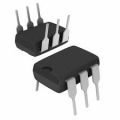
There are plenty of SSR's available but would need to experiment to find the right one. I would suggest a Vishay VOR1121A6 available from Mouser. If you are up to the task 5 of those could be mounted on a perf board, only requires one additional resistor to drive each SSR.
1668440707101.png
 
Last edited:

Reloadron

Joined Jan 15, 2015
7,903
I doubt that inverter can deliver 100ma for each EL wire. Looking at 500ma max driven from two AA batteries.
I think a SSR will work just not the one the TS is currently using.
Yes, I agree with that. However 100 mA is from the data sheet for the SSR data sheet for what the thread starter has. So yes, in conclusion I don't see that SSR working out and would use what you suggested.

Ron
 

Reloadron

Joined Jan 15, 2015
7,903
But since the module outputs 140 VAC, wouldn't you need a smaller resistor to ensure you get the 100 mA minimum current?

However, I think it's a mute point.
Yep, moot point and thank you for pointing that out. I would take the suggestion in post #28.
There are plenty of SSR's available but would need to experiment to find the right one. I would suggest a Vishay VOR1121A6 available from Mouser. If you are up to the task 5 of those could be mounted on a perf board, only requires one additional resistor to drive each SSR.
View attachment 280665


That should work fine.

Ron
 
Top