Relay shield for arduino problems

Thread Starter

Killerbee65

Joined May 15, 2017
256
I would not but only because of concerns as to what the motor current draw is and how much current can be drawn on they pin also if this is a small brush type motor the noise it would put in the system. I am not saying it won't work. If this is a 5 volt motor with a low current draw it will likely work. Since I have not read every post and if the motor specs were covered I don't know them, sorry. Anyway will it work? Likely if the motor has the right specs. Will I suggest doing it? No, but only for the reasons stated.

Ron

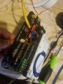
Here's the link to the motors I use:
Cylewet 2Pcs Gear Motor Dual Shaft for Smart Car Robot Arduino (Pack of 2) CYT1037 https://www.amazon.com/dp/B01N9MS3UZ/ref=cm_sw_r_cp_apa_i_KyQCEbXSND0RP
 

djsfantasi

Joined Apr 11, 2010
9,156
So questio

Could I possibly hook up the 5v pin to NO and connect one motor connection to COM and the other to the corresponding points on the board? (7, 6, 4, 5)
Nope.

The corresponding points on the board are used to switch the four relays on and off.

Personally, I’d connect the 5V pin to common. And the NO pin of each relay to each motor.

As I described in post #23, the other motor connection would go to ground.

I can’t see the schematic, but the pins 7,6,4,5 would go to input pins on the relay shield. Actually, since it’s a shield, I expect those pins to be wired already.

UPDATE: There apparently is a lot of missing understanding on your part. And I am struggling to explain it to you.

Things like:
  • The definition of Arduino pins
  • What is the definition of a shield
  • Arduino/shield power requirements
  • Relay power requirenents
  • Load (motor) power requirements
  • How to switch a load with a relay
  • How to control a relay on a relay shield
  • How to protect against back EMF of a motor
  • ...
Get an idea of the challenges I face explaining this to you?

Sorry, after reviewing this list, I don’t think I can help. I’ll still follow your thread. But hopefully someone can explain to you how you should proceed.
 
Last edited:

Thread Starter

Killerbee65

Joined May 15, 2017
256
Nope.

The corresponding points on the board are used to switch the four relays on and off.

Personally, I’d connect the 5V pin to common. And the NO pin of each relay to each motor.

As I described in post #23, the other motor connection would go to ground.


I can’t see the schematic, but the pins 7,6,4,5 would go to input pins on the relay shield. Actually, since it’s a shield, I expect those pins to be wired already.

UPDATE: There apparently is a lot of missing understanding on your part. And I am struggling to explain it to you.

Things like:
  • The definition of Arduino pins
  • What is the definition of a shield
  • Arduino/shield power requirements
  • Relay power requirenents
  • Load (motor) power requirements
  • How to switch a load with a relay
  • How to control a relay on a relay shield
  • How to protect against back EMF of a motor
  • ...
Get an idea of the challenges I face explaining this to you?

Sorry, after reviewing this list, I don’t think I can help. I’ll still follow your thread. But hopefully someone can explain to you how you should proceed.
The only things I have trouble following are the last 4 points you made, I actually tried to look it up and it was the same situation, nothing could really give me a "dumbed down" version :).

The only things I have trouble following are the last 4 points you made, I actually tried to look it up and it was the same situation, nothing could really give me a "dumbed down" version :).
Also iv tried what you said to do in post 23 and the arduino and the shields just shot off completely
 

Reloadron

Joined Jan 15, 2015
7,501
Arduino Shields What is a Shield? Not a bad read on the use of shields.

Your motors are common hobby type brush type motors. Motors aside when you stack your Atduino Uno, battery pack and the relay board you say everything works. The relays click on and off and the relay indicator lights on the board illuminate and extinguish? That all works correct?

While your motor current isn't all that high I would power the motors from a separate source, like a 6 volt battery. Anyway before we worry about that everything I mentioned up to that point works, correct?

Ron
 

djsfantasi

Joined Apr 11, 2010
9,156
Could you provide a link to the relay shiekd
Thank you for responding, yes I have seen that the code and hardware work. The problem I am running into is that I have a recharable energy shield and I want to be able to use it as an external source to power the relay.
What do you mean by “power the relay”? Seriously... It means one thing to me but I can see that you may be thinking something else.

Do you mean providing power to the relay coil in addition/ replacement to the power supplied to the relay by the relay shield?

Or do you mean providing power to the relay contacts in order to switch power to the motors?

Thanks in advance for clarifying this point.
 

ebeowulf17

Joined Aug 12, 2014
3,307
Ok, here are two different ways of graphically representing the circuit for pulling power for the motor out of the power shield (this assumes you've got Arduino, Power Shield, and Relay Shield all stacked up and fully connected to each other, presumably in that order.)
AAC-arduino-relay-shield-motor-2.png

AAC-arduino-relay-shield-motor-1.png

Now, if this is how you had things wired when you say it shut off completely, then you're probably going to need separate batteries for powering the Arduino and the motor, or perhaps a single battery with higher output voltage, and then separate voltage regulators for the two loads. As others have already pointed out, motors are very "noisy" loads and that noise can very easily cause sensitive microcontrollers (the brain of the Arduino) to reset.

***EDIT: I forgot that I definitely should've included a diode in parallel with the motor, or maybe an RC snubber, perhaps even both. I'll try to come back later and post updated drawings, but I'm on kind of a hectic schedule right now, so no promises on timing.
 
Last edited:

djsfantasi

Joined Apr 11, 2010
9,156
The only things I have trouble following are the last 4 points you made, I actually tried to look it up and it was the same situation, nothing could really give me a "dumbed down" version :).
Here are the last four points with an explanation.

  • Load (motor) power requirements What voltage will the motor run at? And what are the startup and running current (amps) required.
  • How to switch a load with a relay A relay has two contacts to a coil. When power is applied to the coil, the contacts change position, like a switch. The contacts are wired like a switch to switch a load.
  • How to control a relay on a relay shield By setting pins 4-7 on the Arduino high, the relay contacts change position. By setting them low, the contacts return to their normal position.
  • How to protect against back EMF of a motor (Don’t worry about this yet) A DC motor that doesn’t change direction can be protected by connecting a diode cathode to the positive side; anode to ground. Your shield may do this, but you need to know in case the Arduino starts acting improperly.
 

Thread Starter

Killerbee65

Joined May 15, 2017
256
Could you provide a link to the relay shiekd


What do you mean by “power the relay”? Seriously... It means one thing to me but I can see that you may be thinking something else.

Do you mean providing power to the relay coil in addition/ replacement to the power supplied to the relay by the relay shield?

Or do you mean providing power to the relay contacts in order to switch power to the motors?

Thanks in advance for clarifying this point.
Providing power to the relay contacts.

What do you mean by “the shields just shot off completely”?

Oh, did you mean “shut off”?
Oh, yes my apologies I have auto correct turned on and I must have missed it. But yes it shut off.

Ok, here are two different ways of graphically representing the circuit for pulling power for the motor out of the power shield (this assumes you've got Arduino, Power Shield, and Relay Shield all stacked up and fully connected to each other, presumably in that order.)
View attachment 201833

View attachment 201832

Now, if this is how you had things wired when you say it shut off completely, then you're probably going to need separate batteries for powering the Arduino and the motor, or perhaps a single battery with higher output voltage, and then separate voltage regulators for the two loads. As others have already pointed out, motors are very "noisy" loads and that noise can very easily cause sensitive microcontrollers (the brain of the Arduino) to reset.
What does a "noisy" load mean?

Here are the last four points with an explanation.

Thank you for the explanations!
 

Thread Starter

Killerbee65

Joined May 15, 2017
256
So I just remembered something and it might help out a bit. I used to do this program called ROV, or remotely operated vehicle, where we built small submarine like vehicles. Anyways I remember building the remote and the way it works is that the remote has various terminals for the motors to connect to. Both motor leads connected into the terminal and that was how the motor would turn on. I want to do something similar to that and I think that is where my confusion stems from. I know you don't have enough information and I'll try my best to get it to you but as you may know all schools are shut down and the information I need is at my school so please bear with me. I hope this might spark some ideas!
I haven't found the board itself but I did find what the controller is all and what it might bring with it:

https://seamate.org/collections/replacement-parts/products/seamate-pufferfish-control-box-kit-rev-7
 

Reloadron

Joined Jan 15, 2015
7,501
Oh, yes my apologies I have auto correct turned on and I must have missed it. But yes it shut off.
My own observation with that symptom is that something overloaded the supply. Could have been many things like a mistake in wiring or an excessive load. I asked you to just stack the three boards in a sandwich and see if the relays operate and the indicator lights work. Have you done that?

Motors, especially small brush type motors, generate noise. If you have ever watched the brushes you see tiny blue arcs and sparks. The brushes running on the commutator produce "noise" on the DC line. Micro-Controllers like an Arduino hate noise. Noise causes ill effects like resets and other strange effects. Unless you can describe what does and does not work in some detail it's about impossible to find a fault.

Ron
 

Thread Starter

Killerbee65

Joined May 15, 2017
256
My own observation with that symptom is that something overloaded the supply. Could have been many things like a mistake in wiring or an excessive load. I asked you to just stack the three boards in a sandwich and see if the relays operate and the indicator lights work. Have you done that?

Motors, especially small brush type motors, generate noise. If you have ever watched the brushes you see tiny blue arcs and sparks. The brushes running on the commutator produce "noise" on the DC line. Micro-Controllers like an Arduino hate noise. Noise causes ill effects like resets and other strange effects. Unless you can describe what does and does not work in some detail it's about impossible to find a fault.

Ron
If I just stack everything like a sandwich it all does work and turn on but as soon as I wired the motor the way described above it shuts off completely.
 

Reloadron

Joined Jan 15, 2015
7,501
If I just stack everything like a sandwich it all does work and turn on but as soon as I wired the motor the way described above it shuts off completely.
OK, and likely because the motor is overloading the available power. So the solution is likely to provide the motor(s) their own power. This way the relay is only acting as a switch. Your relays each have three terminals, a Common and a N/O (Normally Open) and a N/C (Normally Closed). When the relay is active there is a path between Common and N/O. I would find another power source be it a battery or wall wary and connect the + (Positive) out to all of the Commons as in jumper all the relay commons together and they go to the supply +. Tie all of the motor commons (-) together along with the supply negative. They (the negatives) do not need connected to anything else, just battery or wall wart negative to all motor negatives. Each motor + (positive) gets connected to one relay N/O contact.

If everything works as a stack and when the motor(s) are added then the problem lies with either the motor(s) wiring or the motor(s) just present an excessive load.

Ron
 

ebeowulf17

Joined Aug 12, 2014
3,307
For what it's worth, motor specs posted earlier claimed 180mA draw (or something pretty close to that) and battery shield claims 1000mA capability on regulated 5V output, so at least in theory the battery should be able to drive the motor without major voltage sag.

Of course, I'm just talking about average long term figures here - there could still be transient noise spikes due to brush noise, or little split second brownouts right when the motor is starting and requiring extra current to get started.

***EDIT: Just to clarify, I'm talking about the three board stack described earlier, not the latest one with a car chassis added - I have no idea what effect, if any, that addition would have.
 

Thread Starter

Killerbee65

Joined May 15, 2017
256
For what it's worth, motor specs posted earlier claimed 180mA draw (or something pretty close to that) and battery shield claims 1000mA capability on regulated 5V output, so at least in theory the battery should be able to drive the motor without major voltage sag.

Of course, I'm just talking about average long term figures here - there could still be transient noise spikes due to brush noise, or little split second brownouts right when the motor is starting and requiring extra current to get started.
Hopefully if I can get the sketch uploaded it should work. The motors actually came from this car kit so it should all work together
 
Top