Relay controlled with PWM signal

Status
Not open for further replies.

Thread Starter

sherbert1060

Joined Aug 3, 2023
21
Hello and thanks in advance for your help, if I have said anything incorrectly I apologize and will try to supply more details if needed.

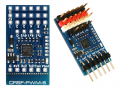
I have a PWM signal that is coming from a radio receiver and the receiver outputs either SBUS or PWM signal. I have a PWM Signal converter that also takes the radio signal and converts it to PWM, this may or may not be needed but I think the principal is the same with either one that I use.

I would like for the PWM signal, when triggered by my radio switch, to supply power to the relay. I have looked into several options for the relay and might need to use a solid state relay but I'm not sure. I have also found relays that will trigger with a PWM signal but they only go to 30 amps and I need 50-65amps so these relays might not work. I could possibly have this relay trigger a bigger relay if needed but I'm trying to be conscious with weight on this. I'm afraid that if I send the PWM signal directly to the relay it will buzz and constantly be switching on and off. I have seen cases where people use a capacitor or mosfet to resolve this issue and that might work but again I'd like to keep the weight down.

I am going to try this on my bench shortly so I guess I'll find out the hard way if this works or not but do you think that the PWM signal sent to the relay will fry the relay or cause contact welding? My next test is to try using a 4.7uf capacitor and see if the relay will stop buzzing (if it does but I think it will). After that I'm thinking I'd send the signal to a MOSFET or transistor and allow that voltage to trigger the relay. Does anyone else have a better idea or is this a good plan to start with?

This is for an RC plane, I would like to use a large relay up to 50a and control it with my radio signal, if this was a servo everything would be no problem but I'm afraid sending the PWM signal to a relay thats constantly on for a long period of time is my problem.
 

ElectricSpidey

Joined Dec 2, 2017
3,313
Set up a re-triggerable mono-stable and let that drive the relay or MOSFET.

The relay or MOSFET with a capacitor may also work, but I have seen cases where PWM doesn't like a capacitor as load.

A large relay would probably require a large cap, a MOSFET would require a smaller cap but would also cause a slow turn off.

I would definitely give the relay and cap a try.
 
Last edited:

MaxHeadRoom

Joined Jul 18, 2013
30,564
DC coil Relays can be ran on 50hz/60hz full wave rectified AC without smoothing capacitor , so if the PWM is higher freq. than this, and the signal can supply the relay coil current then you should have no problem
Also this is assuming that the PWM is of a DC switching nature as well.
 
Last edited:

crutschow

Joined Mar 14, 2008
38,332
If you rectify and filter the PWM signal with a diode followed by a capacitor to common, then the output will be basically equally to the peak PWM signal voltage, independent of the PWM duty-cycle.
Would that work for you?
 

LowQCab

Joined Nov 6, 2012
5,101
You should never use a Relay for anything on an RC-Plane or Quad,
they are ridiculously heavy, and weight is the enemy of anything that flies.

What kind of Load do You intend to switch on an RC-Plane that is not the Motor(s) ?
.
.
.
 

KeithWalker

Joined Jul 10, 2017
3,603
Why do you want to just switch the motor on or off? Is the motor brushless? With a PWM signal and an RC motor controller, you would have full control of the motor speed.
If you really only want to switch it on or off and it's a brushed motor, use a diode, capacitor and resistor on the gate of several power MOS FETs in parallel.
 

MisterBill2

Joined Jan 23, 2018
27,210
First of all, you simply do not drive a relay with a PWM signal, because a relay id not the device to use. A relay is an ON/OFF device and is never intended to operate at any reasonable PWM frequency. A relay may switch as fast as one cycle per second, although usually slower than that
A PWM frequency may be as low as a few hundred hertz.
So now please describe the control you want to achieve, instead of asking us to cobble a way to do something that really will not work. This site has a multitude of very experienced folks, many who are very smart and creative as well, and willing to help.
What seldom works is to demand a way to make an unsuitable scheme function in a way that is not possible.
 

Thread Starter

sherbert1060

Joined Aug 3, 2023
21
DC coil Relays can be ran on 50hz/60hz full wave rectified AC without smoothing capacitor , so if the PWM is higher freq. than this, and the signal can supply the relay coil current then you should have no problem
Also this is assuming that the PWM is of a DC switching nature as well.
Yes I will be using a 6S or 4S battery so around 16-24v nominal. I usually have between 3.7v-4.2v per cell. Thanks, that's what I was going to try first but I figured the signal wouldn't be strong enough and would make the relay buzz.
 

Thread Starter

sherbert1060

Joined Aug 3, 2023
21
If you rectify and filter the PWM signal with a diode followed by a capacitor to common, then the output will be basically equally to the peak PWM signal voltage, independent of the PWM duty-cycle.
Would that work for you?
Yes I think this is what I had in mind. I was hoping that the relay would get a somewhat constant feed, but when I started working on this I didn't/don't fully understand PWM and I didnt realize it was a wave. Thanks, I'll try this as well, do you think I should try to use this as a low voltage/low amperage signal and let the output control a second relay (5-10a or less maybe) that supplies the proper power to my main solenoid/relay (the 50amp one)? I'm getting 4V5 voltage on the PWM converter at this point so I only have a small pad to solder too and can only use a small wire. I doubt the converter can handle a very large load and I'm kind of worried the power required to trigger a 50a relay, traditionally, might be too much? I hope that came out right and wasn't too confusing. This also led me to considering the transistor or MOSFET as the "first relay", and the power from that would trigger the rest but I'm not sure if one way would be better than the other.

One thing I'm worried about that I haven't mentioned here is, I'm not sure if the relays I'm using are for continuous use or not. Some of them say they can only be on a few milliseconds and others have no time frame listed at all. If this loses power, or if the relay fails the plane will drop out of the sky.
 

Thread Starter

sherbert1060

Joined Aug 3, 2023
21
I would recommend a SSR. Something like this if the PWM output is strong enough. Otherwise a transistor or mosfet can drive the input to the SSR.
View attachment 299813
Its funny that you used this model for the picture, I ordered a SSR-60 DD and it just came in today. I'll try this out as well, any suggestions on the capacitor in your drawing, or the resistor size in the drawing? I'm sure you'd need some voltages and amperage to do proper calculations but I was just curious if you have any tips before doing that math.
 

Thread Starter

sherbert1060

Joined Aug 3, 2023
21
Why do you want to just switch the motor on or off? Is the motor brushless? With a PWM signal and an RC motor controller, you would have full control of the motor speed.
If you really only want to switch it on or off and it's a brushed motor, use a diode, capacitor and resistor on the gate of several power MOS FETs in parallel.
Thanks for the input but I'm not trying to switch the motors on or off or any motor at all. I'm not sure if you have any automotive experience, but to me its similar to how a starter solenoid works in a car. Instead of using the key to send voltage to the solenoid and then supply power to the starter, I want to use my radio signal as the key and the PWM signal goes to the relay similar to how the key switch supplies voltage to the starter solenoid and allows current to pass through to the starter. I will be posting a youtube video soon on how this all works and what I plan to use it for but I don't really want to give away the specifics yet. I havent seen anything like this on the market yet and if its possible I'd rather not give it all away, even though I might have already.
 

KeithWalker

Joined Jul 10, 2017
3,603
Thanks for the input but I'm not trying to switch the motors on or off or any motor at all. I'm not sure if you have any automotive experience, but to me its similar to how a starter solenoid works in a car. Instead of using the key to send voltage to the solenoid and then supply power to the starter, I want to use my radio signal as the key and the PWM signal goes to the relay similar to how the key switch supplies voltage to the starter solenoid and allows current to pass through to the starter. I will be posting a youtube video soon on how this all works and what I plan to use it for but I don't really want to give away the specifics yet. I havent seen anything like this on the market yet and if its possible I'd rather not give it all away, even though I might have already.
You mentioned in your initial posting that this is for a model plane. I am confused. Is this for remote starting an internal combustion engine?. If so, RC remote starters are available on e-bay and other sites, ready made and tested.
 

Thread Starter

sherbert1060

Joined Aug 3, 2023
21
Here's a test circuit to see if the PWM is adequate without amplication.
This is for the PWM directly from the receiver, no converter.
View attachment 299820
Using the output from the converter.
View attachment 299821
I apologize if I said this incorrectly, 4V5 is a name on some of our electronics for RC stuff and its 4-9v but I think its supposed to be 5v nominal and can range from 4-9v. If you can see the image below this is one of the components I'm using, there are 6 channels of output, the Black row of pins are grounds, the Red pins are all positives and supplied by the same 4V5 power (some have an onboard BEC some require an external BEC to supply this power), and the white pins are the signal. I haven't used this piece of equipment yet but I believe the red and black pins are the constant supply and the white pin is the signal to trigger the servo or if this is connected to an ESC it could power a motor. I dont need either of those options though, I was hoping to use this output to control my relay and switch it on and off.

An example would be if I wanted to turn on and off a second camera or VTX, or maybe some LEDs, or a Smoke trigger on a plane, so instead of sending the signal to the servo I wanted to send it to a relay controlling the power to this accessory. I think my main problem is there isn't a converter for this specific application, so I'm having to use the PWM signal since its the only thing I think I can trigger with a switch from my radio. That's what led me here to converting the PWM signal from the radio (when a switch is flipped) that gets sent to a relay, supplying power to my accessory. Did that help any?
 

Attachments

Thread Starter

sherbert1060

Joined Aug 3, 2023
21
You mentioned in your initial posting that this is for a model plane. I am confused. Is this for remote starting an internal combustion engine?. If so, RC remote starters are available on e-bay and other sites, ready made and tested.
One of the options could be using it on a model plane, I have a few other uses but I don't think its quite the same as starting a combustion engine, as I think those are for short burst of power and this is intended to be constantly on almost the entire time I'm flying. I have looked for solutions like this but haven't found anything yet, I'll check on RC remote starters to see if its similar. Thanks
 

Thread Starter

sherbert1060

Joined Aug 3, 2023
21
One of the options could be using it on a model plane, I have a few other uses but I don't think its quite the same as starting a combustion engine, as I think those are for short burst of power and this is intended to be constantly on almost the entire time I'm flying. I have looked for solutions like this but haven't found anything yet, I'll check on RC remote starters to see if its similar. Thanks
1691110518191.png

I found this, which is close but not high enough voltage and not high enough amperage and I dont need two relays, but maybe I can use this to trigger a larger relay that can handle 50a or more. Thanks, I still would like to try and build this on my bench without buying something else. It will make it harder to trim weight if I'm not building it, ease of use isn't my primary focus here. I'm considering building an entire PCB with all of the components (some I havent mentioned) built into the board. I'm nervous to describe it all here as I dont want to totally give away my idea and design. Nothing like this exists in our little FPV/RC community that I have found yet, even if I don't design or patent it I'd like to be able to reveal it all at once on a youtube video explaining everything and I'm trying not to give it all away before then. Maybe its nothing and a flop but the only issue I've found yet (besides weight) is the PWM signal feeding into the relay, the rest I've already worked out. Some people may be guessing what I'm doing and I dont mind, as I get it finished I'll post on here a link to the youtube video so everyone can shred me to pieces like MisterBill2 did earlier lol
 

Thread Starter

sherbert1060

Joined Aug 3, 2023
21
You should never use a Relay for anything on an RC-Plane or Quad,
they are ridiculously heavy, and weight is the enemy of anything that flies.

What kind of Load do You intend to switch on an RC-Plane that is not the Motor(s) ?
.
.
.
What would be a better way to control 25v/50a, in this situation, than a relay? Weight is definitely my enemy and a huge problem here but I'm not sure how else to break the continuity on a 50a DC circuit with something tiny. I need the relay to be on for several minutes and then switched back off with my radio, so I know I'm not an expert but I couldn't find anything other than a relay or a Solid State Relay to break the continuity.

Also, for now I'm just trying to see if I can even make my idea work on the bench. Props are off for testing at this point, and the components are just laying on the bench wired together loosely, its not a finalized design. I cant really explain it yet without fully giving it away, but like I said in the other posts I will be making a youtube video and I'll be happy to post it here once I'm done. I guess the closest example would be, imagine its a big RC plane, it has a big flood lamp on it and I want to turn on and off the light with my radio. This is hypothetical but the light would need a lot of power compared to a normal servo or something, so imagine there's a second battery source in the plane and I want to control a relay for that light with my radio. This is not what I'm building but comparable in how it executes. I'm not flying at night or hooking a giant light to my plane so I don't want anyone going off on that tangent, lol, just an example.
 
Last edited:
Status
Not open for further replies.
Top