 Facebook
 Google
 GitHub
 Linkedin
Hi,
I am trying to repair a relay driver board that has dual 78SR112HC regulators on it (which are obsolete) for power regulation I believe. The board mainly consists of ULN2803 drivers and relays.
1) is there some advantage over the 78SR112HC vs. say a "standard" 7812? I don't see anything in the data sheets (or I am overlooking it).
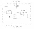
2) trying to understand the reason behind how they are hooked up together. Pin 1 is the input, 2 ground, and 3 the output of the 78SR112HC. See attached picture
- Now the manufacturer has connected the devices together on a daughter board with 3 connections: input, output and ground. Same configuration as the 78SR112HC (or 7812) pinout.
- What is the purpose of device #2? Is it there for some sort of feedback control?
3) can I simply install 2 7812's (or even just use 1 in place of this daughter card?
Thank you for any info/suggestions.")
I am trying to repair a relay driver board that has dual 78SR112HC regulators on it (which are obsolete) for power regulation I believe. The board mainly consists of ULN2803 drivers and relays.
1) is there some advantage over the 78SR112HC vs. say a "standard" 7812? I don't see anything in the data sheets (or I am overlooking it).
2) trying to understand the reason behind how they are hooked up together. Pin 1 is the input, 2 ground, and 3 the output of the 78SR112HC. See attached picture
- Now the manufacturer has connected the devices together on a daughter board with 3 connections: input, output and ground. Same configuration as the 78SR112HC (or 7812) pinout.
- What is the purpose of device #2? Is it there for some sort of feedback control?
3) can I simply install 2 7812's (or even just use 1 in place of this daughter card?
Thank you for any info/suggestions.
Attachments
-
 81.2 KB Views: 8


