Reducing EMF from unipolar stepper motor

Thread Starter

Doceave

Joined Nov 16, 2019
49
Hi there all

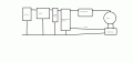
I have build a device which needs to rotate a tube slowly (using a 28BYJ-48 unipolar stepper motor; driven by a ULN2003A) while an ADC (ADS1115 connected to microcontroller by I2C) collects data from a number of sensors' outputs.

My problem is noise collected by the ADC that is worse when the motor is running ---- this results in a saw-tooth pattern superimposed on the signal collected.

The motor itself is distant to the ADC and sensors so thus I assume the magnetic fields in the vicinity of the motor are not at fault.

More likely causes for this phenomenon:
> Unstable power supply to sensors which result in fluctuations in output signal
- This I hope to address by supplying the ADC and sensors with their own linear regulator and some filtering caps

My question is whether or not the circuit would benefit from additional flyback diodes (over and above those within the ULN2003)?
> If so, also some advice as to an appropriate (smallest possible SMD) diode and schematic for connection.

1585471848704.png

Thanks in advance.
 

Thread Starter

Doceave

Joined Nov 16, 2019
49
I understand that placing additional flyback diodes over each phase would result in each phase turning off more slowly --- but how detrimental this likely to be if the motor is typically taking a step every 5ms?
 

Thread Starter

Doceave

Joined Nov 16, 2019
49
hi D,
Your diagram of the ULN is not correct.
Pin #9 should be connected to the supply line.?
E
Thanks E

I just grabbed a pic of the ULN2003 internals --- clearly a bad one.

In my circuit COM is indeed supply:
1585476018035.png
The question thus:
> Is it necessary / possible / recommended to add additional flyback diodes in order to eliminate any contribution by the stepper to noise at the ADC located elsewhere in the circuit?
 

ericgibbs

Joined Jan 29, 2010
18,848
hi D,
Do you have a copy of the complete circuit that you could post or a photo image of the project, so that we can check the layout.?
E
 

Thread Starter

Doceave

Joined Nov 16, 2019
49
Sure thing E... I would be most appreciative of your review of it:
Schematic_ACT_Mainboard V2_ACT_Mainboard V2.0_20200329122842.png

Additional details:
> The heaters, which attach at headers KR and KL are not responsible for the noise
- When on and off, there is no change in noise levels
> The ADC is an ADS1115 (there are two) -- these are on a "sensor PCB" attached to header Sense-L and Sense-R
> The motors are 28BYJ-48's attached the obviously named headers
> The long headers in the middle of the diagram represent attachment point for an ESP32 Dev board ---- I know they are draw the wrong way around
- But are correct on the PCB and the ESP behaves as it should :)

The output from the ADC looks like this:
1585477989107.png
> There are different unwanted sorts of noise here
- Large spikes that appear at seemingly random intervals
- Regular, saw-tooth patterns noise that I suspect eminate from the ULN2003/Stepper motors

In the trace above the sensors should be putting out a flat line with no obvious change in output (as input should be constant)

Any advice / ideas would be most welcome. I have identified a good few mods that will be built into the next version but the more suggestions the better :)
 

MrAl

Joined Jun 17, 2014
11,472
To clamp the coil back emf you need a diode as shown across coil B.
However, the supply must be able to take the current without changing the voltage too much so you need a good filter cap on the +Vcc line and enough load to absorb the power.
You can also place a resistor in series with the diode to get it to dissipate the coil energy faster.
 

Attachments

Thread Starter

Doceave

Joined Nov 16, 2019
49
The PCB which houses the ADC and sensors is show below:
Schematic_ACT_Sensor_Assembly V2.0(SMD)_ACT_Sensor_Assembly V2.0(SMD)_20200329125711.png
As before, any suggestions for noise reduction in this component of the circuit would be most appreciated.

Additional notes:
> The LED and phototransistor at the top are for detecting presence of a sample
> The diode attached to Vc --- a coil, attaches to the diode itself which creates a steady magnetic field --- a constant current flows here during the data collection
> Inputs to the ADC are linear output hall effect sensors
 

ericgibbs

Joined Jan 29, 2010
18,848
hi,
Even though the general appearance of the noise appears random, there are many close matches along the plot.
Also the lower limit of the 'square' wave, appears to be changing.

My best estimate would be power rail decoupling/smoothing problem and stepper motor noise.

Try suppression diodes close to the stepper motor coils.

E
 

Attachments

Thread Starter

Doceave

Joined Nov 16, 2019
49
hi,
Even though the general appearance of the noise appears random, there are many close matches along the plot.
Also the lower limit of the 'square' wave, appears to be changing.

My best estimate would be power rail decoupling/smoothing problem and stepper motor noise.

Try suppression diodes close to the stepper motor coils.

E
Got it. :) Will implement.

Is there a generic decoupling capacitor combination that you can recommend for placing:
> Over the power input to the device?
> Over power supply from regulator to the ADC and hall effect sensors?
Perhaps a combination of values?
 

Marc Sugrue

Joined Jan 19, 2018
222
Hi, I have a couple of suggestions you may or may not have looked at

If you have multiple PCBs is it possible what your seeing is ground bounce? How well coupled is the GND on your main PCB to your ADC pcb? I take it you have a complete ground planes etc? If not it could help.

Capacitance, their doesn't seem a great deal on the supply to you Motor. You may want to consider a relatively large electrolytic at the supply to your motor this will keep the pulse currents local to the motor output. You may need a couple of Ceramic capacitors in parallel to deal with the RF as the electrolytic will only be good for about 500Khz.

Another suggestion would be to Seperate VCC and MotorVCC with a reasonable inductance, coupled with the Capacitance above this will form an LC filter and will keep the Vcc of the logic quiet

If possible try and keep the motor drive electronics close to the motor along with LC as suggested above as close to the motor as is possible. This will minimise the high current switching paths and reduce your issues. Also try and keep Interconnecting wires tight together to minimise radiated RF
 
Last edited:

Thread Starter

Doceave

Joined Nov 16, 2019
49
Another suggestion would be to Seperate VCC and MotorVCC with a reasonable inductance, coupled with the Capacitance above this will form an LC filter and will keep the Vcc of the logic quiet
This is a great idea.... I found some proposed schematics for this purpose:
1585484790690.png
This one describes a filter over a buck type switching regulator.

I will order a range of components for L1, L2, and C1-3
Would you kindly make recommendation for starting values for the above?
> The MP1584 buck regulator I have opted to use switches at 1.5Mhz


I have also added caps for the motor power supply to the list :)
 

Marc Sugrue

Joined Jan 19, 2018
222
This is a great idea.... I found some proposed schematics for this purpose:
View attachment 202800
This one describes a filter over a buck type switching regulator.

I will order a range of components for L1, L2, and C1-3
Would you kindly make recommendation for starting values for the above?
> The MP1584 buck regulator I have opted to use switches at 1.5Mhz


I have also added caps for the motor power supply to the list :)
Precisely, As i see it your circuit is the Noise Sensitve part feeding a noisy system (the stepper circuit). I would suggest using the PI arrangement (C3, C1, and L2) between your circuit and the motor power which gives you some flexibility to remove parts as necessary. I don't know the spec of your motor but once you know the peak current and frequency of operation you can calculate filter components and do a quick simulation

For LC Filter Fc = 1/2 x PI x sqrt(L*C)

Just to clarify i attach a very rough block diagram.

To filter the motor could you tell us the motor voltage, peak current & operating frequency of motor please? This will alow to come up with some values for the motor filter.

For the DC/DC inpit filter we'd need to fill in the blanks

Input Volts Min
Peak Input Current @ Low Vin
Operating Frequency = 1.5Mhz


For the Output filter

Output Voltage =
Output Peak Current =
 

Attachments

Last edited:
Top