Facebook
 Google
 GitHub
 Linkedin
Hi
I have a little prodject going on with my 3D printer CR-X from creality.
I want to put an auto bed leveling on it, but my circuit bord only supports 12V and the power supply is 24V
I tryed using the Voltage devider with 2 simmular resistances but my Capacitive Proximity Sensor uses about 200mA so the voltage drop is to much.
So my question is is there some way to modify the board that I'm using? Change the resistors? I could always use a 12V power suply from the outlet or an power drowngrader, but I want it to be a complet kitt whitouth the extra parts.
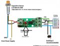
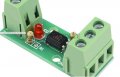
The board
https://www.ebay.com/itm/12V-1-Chan...e=STRK:MEBIDX:IT&_trksid=p2057872.m2749.l2649
https://www.thingiverse.com/thing:2906283/comments
The Sensor
https://www.ebay.com/itm/DC6-36V-3-...e=STRK:MEBIDX:IT&_trksid=p2057872.m2749.l2649
The printer
https://www.creality3d.cn/creality3d-cr-x-p00252p1.html
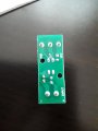
The components on the board
R1= Brown, Black, Red, Gold = 1Kohm+-5%
R2=Brown, Black, Orange, Gold =10Kohm +-5%
Led: Probably a normal 5V led or something?
Optocoupler
http://www.everlight.com/file/ProductFile/EL817.pdf
Also se picture
Please correct me if I'm wrogn when you look at the pictures of the resistances and let me know if you need more information
I have a little prodject going on with my 3D printer CR-X from creality.
I want to put an auto bed leveling on it, but my circuit bord only supports 12V and the power supply is 24V
I tryed using the Voltage devider with 2 simmular resistances but my Capacitive Proximity Sensor uses about 200mA so the voltage drop is to much.
So my question is is there some way to modify the board that I'm using? Change the resistors? I could always use a 12V power suply from the outlet or an power drowngrader, but I want it to be a complet kitt whitouth the extra parts.
The board
https://www.ebay.com/itm/12V-1-Chan...e=STRK:MEBIDX:IT&_trksid=p2057872.m2749.l2649
https://www.thingiverse.com/thing:2906283/comments
The Sensor
https://www.ebay.com/itm/DC6-36V-3-...e=STRK:MEBIDX:IT&_trksid=p2057872.m2749.l2649
The printer
https://www.creality3d.cn/creality3d-cr-x-p00252p1.html
The components on the board
R1= Brown, Black, Red, Gold = 1Kohm+-5%
R2=Brown, Black, Orange, Gold =10Kohm +-5%
Led: Probably a normal 5V led or something?
Optocoupler
http://www.everlight.com/file/ProductFile/EL817.pdf
Also se picture
Please correct me if I'm wrogn when you look at the pictures of the resistances and let me know if you need more information
Attachments
-
 47.1 KB Views: 13
 -
 57.4 KB Views: 8
 -
 108.3 KB Views: 6
 -
 116.2 KB Views: 7
 -
3.6 MB Views: 5