Facebook
 Google
 GitHub
 Linkedin
Hi
I need help with this project please
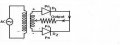
single phase full wave control rectifier 2 pulse with load 10 watt
I need to design the circuits and explain it
help m
I need help with this project please
single phase full wave control rectifier 2 pulse with load 10 watt
I need to design the circuits and explain it
help m