Reading pinout on to-92 case transistor datasheet (which side is the curved side)

Thread Starter

beginnersluke

Joined Aug 26, 2015
35
I've decided to ask since I couldn't find anything I was 100% sure of on the interwebs and this forum.

(Sorry, I feel like this is a dumb question, but I don't want to make a mistake and am only 98% sure myself.)

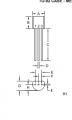
Please see the attached snipped from a datasheet for a 2N5088 transistor.

The diagram where the pins are labelled it shows a double rectangle for the body of the transistor. This means the curved side is facing the reader in the diagram, correct?

So if the curved side of my transistor is facing me, the leads are (from left to right) E, B, C?


I'm pretty sure the diagram matches the one below it since that would be logical, but I've seen crazier things in my life.

The biggest reason I'm not 100%% sure is simply googling the pinout results in a huge majority showing an opposite pin configuration (but I know they can vary).

I just wish the datasheet had a nice angle drawing so I could be sure.
 

Attachments

BobTPH

Joined Jun 5, 2013
8,958
Nope, the flat side is toward the viewer.

If you look at the top view, the transistor's shape is a cylinder with a vertical slice taken off a little less then half way through. The double lines are because you are seeing the edge of the flat part (cut out) as well as the larger width of the cylinder. If you were looking at the round side, the inside lines would be dotted since they cannot be seen directly.

I took mechanical drawing in 7'th grade. Everyone in the class copied my drawing because I was the only one who understood how to do it. And I got a C in the class because my drawings were all smudged. Life is not fair.


Bob
 

Thread Starter

beginnersluke

Joined Aug 26, 2015
35
So you're saying that if the curved side is facing me, the leads are Collector, Base, Emitter?

Correct?

This means the diagrams don't match! That is, in the top diagram, the leads are (left to right) E,B,C, but the diagram just below they are (left to right) C,B,E.

(As an aside, I see what you're saying as far as the drawing. To add a source of confusion though, the actual transistor does not widen, so if you look at it, you only see the flat face.)

Thanks!
 

OBW0549

Joined Mar 2, 2015
3,566
How about using a multimeter to find out which is base, collector and emitter?
That can tell you which pin is the base lead, but it won't do a very good job of telling emitter from collector.

Always read the data sheet. And if you can't find a data sheet for it, throw it in the trash.
 

Zeeus

Joined Apr 17, 2019
616
That can tell you which pin is the base lead, but it won't do a very good job of telling emitter from collector.

Always read the data sheet. And if you can't find a data sheet for it, throw it in the trash.
But base-collector junction is slightly larger than base-emitter

= less voltage drop across the former to the latter

Okay, will read datasheet but what if "we are lost on a desert island with transistors and multimeter and need to summon our rescuers with a transmitter"..We give up? or try figure it out?

Edit : have tried with more than 5 transistors..Yet to fail
 
Last edited:

Zeeus

Joined Apr 17, 2019
616
Put a message in bottle: "Please send data sheet for 2N5088 transistor. Thx!"
lol

btw, how about you continue your road trip admiring the waitresses?
but remember : "He who looks at a woman to lust after her hath committed adultery with her already in his heart" Knowledge directly proportional to holiness?

= be good!
 

crutschow

Joined Mar 14, 2008
34,431
The diagram where the pins are labelled it shows a double rectangle for the body of the transistor. This means the curved side is facing the reader in the diagram, correct?
You likely never took mechanical drafting, so here's one rule:
When two views of an object are shown next to each other, one is normally a 90° rotation of the other.
So, in the drawing below, you can see the pins are edge-on (out of the page) in the bottom diagram (if they were hidden pins, they would be a dotted-line), which means the top diagram was rotated 90° to place the pins up .
Therefore, you must be looking at the flat in the top diagram.

Make sense?

upload_2019-6-1_20-16-29.png
 

SLK001

Joined Nov 29, 2011
1,549
Okay, will read datasheet but what if "we are lost on a desert island with transistors and multimeter and need to summon our rescuers with a transmitter"..We give up? or try figure it out?
Don't worry about it, we forgot the power supply.

Put a message in bottle: "Please send data sheet for 2N5088 transistor. Thx!"
The best classic response of all time!
 

MrChips

Joined Oct 2, 2009
30,806
Engineering drawings (like circuit schematics) are intended to communicate without ambiguity.

Mechanical engineering design employs drawings based on an orthogonal projection view (which is different from architectural drawings which use a floor plan).

Think of orthogonal views as looking at the top, bottom, and sides of a box containing the object. The orthogonal views are what you would see as you unfold the box.


The drawing below clearly indicates that you are looking at the transistor view from the bottom. (The bottom view is drawn below the front view.)

The pinout as noted in the datasheet is:

1 - Emitter
2 - Base
3 - Collector


Top