 Facebook
 Google
 GitHub
 Linkedin
Background
Previously I posted a thread about controlling 24V relays with an ESP32. With the help of this forum I now have the control section working correctly.
Unfortunately I am not in the same country as the controller but still need to continue designing even though I am temporarily unable to test.
The purpose of this project is to control a medium sized heating system from a IOT controller. The system is over 30 years and the original controller is no longer working.
There are 4 main pumps that circulate water through the two boilers and around the house. These are running on 200V and are controlled by contactors. They can be placed in auto (controller)/manual (controlled by push buttons)/off mode. The contactors are Mitsubishu UA-AX4.

When in auto mode, the contactors are controllers by 24V relays (Omron MY-2). There are two relays per contactor, one to turn it on and the other for off. These are then connected to the main control board in the house.

Control System
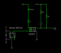
Using an PC817 optocoupler, PNP transistor and Omron MY-2 relays.

Feedback System
In order to know the state of the pumps and additional devices in the system, I need to check whether the contactors or switches are closed.
Distance between the contactors and relays in the boiler room and the controller is roughly 30 meters, single-strand copper around 16/18 gauge.
Previous System
I assume that this is the feedback part of the original controller, using 1 capactor, 2 diodes and 3 resistors for each switch input. But it doesn't power on so I can not test the voltage.

Option 1
Similar to the design I used for the control side, I thought about using 24V controlled with optocouplers. This would then provide some isolation to the micro-controller but I am not sure if it is necessary. TP will be connected either directly to an ESP32 or an IO expander such as MCP23017.

However this would result in the LED either being permanently on or off, with no change based on the actual state of the contactor.
This then lead me to believe that there was either a connection issue or I have selected the wrong type of optocoupler for this purpose. Possibily need either a different CTR value or need to change the resistor values.
Option 2
This option is based on another thread from this forum after researching. 24V with potential divider and/or diodes. But changing the values to be compatible with 3V for the ESP32.
.png")
.png")
Option 3
3V direct from ESP32 throught contactor to a digital input pin. Digital pin set to input and 10K internal pull-up resistor.

This seems like the simplest solution but is it susceptible to noise or voltage drop? What kind of protection is needed (if any)
Conclusion
Please let me know if anyone has designed a controller for a similar system and which, if any, of the options seem the most suitable
Previously I posted a thread about controlling 24V relays with an ESP32. With the help of this forum I now have the control section working correctly.
Unfortunately I am not in the same country as the controller but still need to continue designing even though I am temporarily unable to test.
The purpose of this project is to control a medium sized heating system from a IOT controller. The system is over 30 years and the original controller is no longer working.
There are 4 main pumps that circulate water through the two boilers and around the house. These are running on 200V and are controlled by contactors. They can be placed in auto (controller)/manual (controlled by push buttons)/off mode. The contactors are Mitsubishu UA-AX4.
When in auto mode, the contactors are controllers by 24V relays (Omron MY-2). There are two relays per contactor, one to turn it on and the other for off. These are then connected to the main control board in the house.
Control System
Using an PC817 optocoupler, PNP transistor and Omron MY-2 relays.
Feedback System
In order to know the state of the pumps and additional devices in the system, I need to check whether the contactors or switches are closed.
Distance between the contactors and relays in the boiler room and the controller is roughly 30 meters, single-strand copper around 16/18 gauge.
Previous System
I assume that this is the feedback part of the original controller, using 1 capactor, 2 diodes and 3 resistors for each switch input. But it doesn't power on so I can not test the voltage.
Option 1
Similar to the design I used for the control side, I thought about using 24V controlled with optocouplers. This would then provide some isolation to the micro-controller but I am not sure if it is necessary. TP will be connected either directly to an ESP32 or an IO expander such as MCP23017.
However this would result in the LED either being permanently on or off, with no change based on the actual state of the contactor.
This then lead me to believe that there was either a connection issue or I have selected the wrong type of optocoupler for this purpose. Possibily need either a different CTR value or need to change the resistor values.
Option 2
This option is based on another thread from this forum after researching. 24V with potential divider and/or diodes. But changing the values to be compatible with 3V for the ESP32.
Option 3
3V direct from ESP32 throught contactor to a digital input pin. Digital pin set to input and 10K internal pull-up resistor.
This seems like the simplest solution but is it susceptible to noise or voltage drop? What kind of protection is needed (if any)
Conclusion
Please let me know if anyone has designed a controller for a similar system and which, if any, of the options seem the most suitable
Attachments
-
 68.2 KB Views: 1


