re; any help mppt

Thread Starter

olusola

Joined May 21, 2007
74
well i think the mosfet is not fully closed as in the the voltage been sent to it is still in the high region and hence still drawing some current from the solar module, but operating in the 'very-left' region of the I-V curve and hence low voltage

i also think maybe the algorithm might either not be working that well or the incrementing is really small and hence just dancing around that location.

reasonable?
 

hgmjr

Joined Jan 28, 2005
9,027
olusola said:
i put in the 2nd op-amp because i noticed the mosfet was off and also the voltage output was still negative
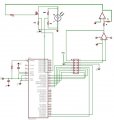
Also I would be interested in an updated schematic showing the placement of the additional opamp you referred to above.

At what point in the circuit was the voltage going negative?

hgmjr
 

Thread Starter

olusola

Joined May 21, 2007
74
because it is quite interesing how quickly it goes from 0 and yes truly draws more current than the fixed resistor ,, but on the other hand, lower voltage and hence - lower power ... oooooooo
 

hgmjr

Joined Jan 28, 2005
9,027
well i think the mosfet is not fully closed as in the the voltage been sent to it is still in the high region and hence still drawing some current from the solar module, but operating in the 'very-left' region of the I-V curve and hence low voltage

i also think maybe the algorithm might either not be working that well or the incrementing is really small and hence just dancing around that location.

reasonable?
I will look a bit closer at the algorithm to see if I can spot a flaw.

By the way you will notice that I am online today. I get every other Friday off so today is that Friday off.

I am available to work on figuring out what is happening pretty much all day. Are you close by the circuitry right now?

hgmjr
 

Thread Starter

olusola

Joined May 21, 2007
74
it went negative on coming out of the first op-amp.
i used an inverting amplifier using a 1k - 1k resistors - so no amplification.
oh, the schematic,.. might take some mins. can i give that to you later .
i need to leave the lab very soon ..
i will continue working elsewhere but now i have to leave here for locking up
 

Thread Starter

olusola

Joined May 21, 2007
74
wow friday off .. coool
yes i am near by the circuitry and well if you want me to try some quick things - why not
thoug i might have to leave it in like 20mins
 

hgmjr

Joined Jan 28, 2005
9,027
because it is quite interesing how quickly it goes from 0 and yes truly draws more current than the fixed resistor ,, but on the other hand, lower voltage and hence - lower power ... oooooooo
It almost sounds like the action of the control signal is inverted from what it needs to be.

Does that make sense to you?

I need to look closer at the algorithm.

hgmjr
 

hgmjr

Joined Jan 28, 2005
9,027
Don't worry about it (leaving, that is). I need to study the algorithm a bit closer now anyhow.

I could still use an updated schematic as soon as you can update it so that I can avoid any confusion.

hgmjr
 

Thread Starter

olusola

Joined May 21, 2007
74
oh, em, i think i should apologise cos the reverse i meant all this while was that it was inverted ... ooooo .. i'm so so sorry

now about the control signal being inverted, em, looks well when i first tried it when it was negative, i was kinda getting voltages but no or very little current, so i'm guessing that was the mosfet on open circuit . - unfortunately i have no results for that.
 

hgmjr

Joined Jan 28, 2005
9,027
oh, em, i think i should apologise cos the reverse i meant all this while was that it was inverted ... ooooo .. i'm so so sorry

now about the control signal being inverted, em, looks well when i first tried it when it was negative, i was kinda getting voltages but no or very little current, so i'm guessing that was the mosfet on open circuit . - unfortunately i have no results for that.
Thanks for the clarification. That's good news cause I was getting really worried that something was hooked up seriously wrong.

hgmjr
 

hgmjr

Joined Jan 28, 2005
9,027
yes will be working on it till is working,
am trying to get weekend access to the lab .
Were you able to get weekend access to the lab?

I have your latest schematic and while I don't think the additional inverting opamp in the control signal path is needed, its presense is not a hinderance to the circuits operation. It just adds another signal inversion in the loop.

hgmjr
 

Thread Starter

olusola

Joined May 21, 2007
74
wow, nice that op-amp has been cleared by the govt (forum!); now is to pursure the implementation of a working code,

yes starting debugging.

well the code, thats what i'm trying to look at now. have seen your comments. so i'm really trying to see what can be done .

thanks
 

hgmjr

Joined Jan 28, 2005
9,027
wow, nice that op-amp has been cleared by the govt ; now is to pursure the implementation of a working code,

yes starting debugging.

well the code, thats what i'm trying to look at now. have seen your comments. so i'm really trying to see what can be done .

thanks
I think the weak link is the brcc (branch on carry clear) instruction in the increment DAC value section of the code. Since the the cp (compare) instruction does not affect the carry bit, this instruction does not have the effect you are looking for. Take a look at the brne (branch on not equal) instruction.

hgmjr
 

Thread Starter

olusola

Joined May 21, 2007
74
Higher_Increase:;
inc DAC_out_L;
brcc Finish;
inc DAC_out_H;
rjmp Finish;

Lower_Increase:;
cbr Move_Status, 0;
inc DAC_out_L;
brcc Finish;
inc DAC_out_H;
rjmp Finish;
i still am trying to understand the use of brne in this situation.
well is it a situation where the software wont put a carry and hence do you suggest we address this situation by ugoin

Higher_Increase:;
inc DAC_out_L;
cpi DAC_out_L,255
brne Finish;
inc DAC_out_H;
rjmp Finish;
 

hgmjr

Joined Jan 28, 2005
9,027
Rich (BB code):
Higher_Increase:;
    inc DAC_out_L;
    brcc Finish;
    inc DAC_out_H;
    rjmp Finish;

Actually I think all you will need to do is change the brcc instruction to brne and nothing else needs to be added.

The reason is that the inc instruction affects the Z-flag in the Status-Reg and brne tests the Z-flag when the byte goes from 255 to 0.

You have a copy of the ATMEL document that describes the AVR instruction set in detail, right? Take a look at the instructions we are discussing and you will see what I am talking about.

hgmjr
 
Top