re; any help mppt

hgmjr

Joined Jan 28, 2005
9,027
If you don't mind me asking, what are the adverse consequences of not having everything working smoothly in time for your demo tomorrow?

hgmjr
 

Thread Starter

olusola

Joined May 21, 2007
74
well i guess you think the algorithm is ok. so that is good to hear.
i'm not sure how easy it wil be to test it, just probably want to know if it looks logical.


There a few things that need attention but the framework seems workable.
was just gonna ask what you think needs attention? especially since you might be at work, so i know what to look out for .
 

hgmjr

Joined Jan 28, 2005
9,027
well to be honest, marks!
That's is kinda what I suspected was at stake.

can i ask what issues do you forsee?
The main issue I see is the woefull lack of testing time needed to refine the algorithm and establish the optimum update rate for the control loop.

You're doing fine at gaining the knowledge needed to understand what is going on. If you can impress your instructor by convincing him that you are gaining knowledge that will insure that you can successfully complete the assigned task in the alotted time then that may compensate for anything that does not work quite right with the hardware/software.

hgmjr
 

hgmjr

Joined Jan 28, 2005
9,027
To be honest, this would be a good 2 to 3 week task for a seasoned engineer just to get to a workable prototype. To get as far as we have in under a week is not too bad.

hgmjr
 

Thread Starter

olusola

Joined May 21, 2007
74
i really admit, to get this far, really i really appreciate your help. and me taking all your time, for this, i truly am grateful .

this is meant to be a demo, and it is to build more and bigger ones, but my supervisor is a traveller and if its not done now .. ...

thanks
 

hgmjr

Joined Jan 28, 2005
9,027
well i guess you think the algorithm is ok. so that is good to hear.
i'm not sure how easy it wil be to test it, just probably want to know if it looks logical.


was just gonna ask what you think needs attention? especially since you might be at work, so i know what to look out for .
Actually, I just had a thought that might help you out by avoiding the use of an interrupt all together.

Do you have a mandate from your instructor to use an interrupt to do this task?

hgmjr
 

Thread Starter

olusola

Joined May 21, 2007
74
can i just confirm the working of the mosfet.
when you increase the voltage applied to the gate - you get a reduction in the drain-source resistance Rds? or ?
 

Thread Starter

olusola

Joined May 21, 2007
74
there is no mandate for the use of an interrupt. once it can track the maximum power point and follow it, and hold it - then -
 

Thread Starter

olusola

Joined May 21, 2007
74
i can really say its getting late, and i dont want you not getting rest like me,
but i can i just say that i think i made a mistake with the P1>P0

That is the easiest thing of all. In your flowchart you indicate that when P1 > P0 you increment the value you output to the DAC. Incrementing the binary value fed to the DAC will result in an increase in the voltage applied to the mosfet gate. As I indicated, when the voltage increases on the gate more current is drawn from the solar panel by the mosfet active load. If this is consistent with what you want the active load to do then no change to your program logic is required. If not, then all you need to do is change the action from increment to decrement and you are good to go. This is how you invert the sense of the control.
if the voltage increased draws more current, then this if i am sure will not be moving in the right direction of the I-V curve, as i would have thought. so i think i am guessing it would be the reverse

but now so are you sayin that changing the direction will inverse this?
because i would have thought that the result from the DAC is said to be -Vref*(1023/1024) for the maximum 1111111111 and 0 for 0000000000 which should be -10 to 0 in this case.

so will we be sending a negative signal to the mosfet or - sorry i just want to be sure . sorry to hammer on this , i just want to be sure

thanks
 

hgmjr

Joined Jan 28, 2005
9,027
Consider this then.

For now just eliminate the "sei" statement so that ALL interrupts are left disabled.

Next replace the reti "return from interrupt" with an ordinary ret "subroutine return" instruction. That will turn your interrupt service routine into an ordinary subroutine. The label you had for the interrupt service routine was "MPPT". That will now be the label for your subroutine.

Next, go to the forever loop that I suggested you add earlier and inside that loop add the instruction. "CALL MPPT;".

Now what you have is simplified program that just continuously loops and with each loop, it calls your subroutine. The subroutine will take as long as it take to execute and then return. Once it returns from the subroutine it will finish the idle-loop and then call the MPPT subroutine again.

This will get you out of the need to worry about timing for the interrupt service routine.

You may need to add a delay loop inside the idle loop just to kill a little time between calls to the subroutine.

Do you follow my train of thought?

hgmjr
 

Thread Starter

olusola

Joined May 21, 2007
74
yes, that sounds really good.
still wondering how i will make delays though - sorry new to assembly programming.
but sounds good to me anyway!

Olu
 

hgmjr

Joined Jan 28, 2005
9,027
Rich (BB code):
idle_loop:                    // Top of idle loop....
 
    // Delay loop....
    clr Temp;                // Clear register Temp....
inner_loop:
    dec Temp;              // Decrement register Temp...
    brne inner_loop;     // Test & Branch if Temp not equal to 0...
 
    Call MPPT;              // Call subroutine MPPT...
    rjmp idle_loop;       // Loop again...
Here is the code snippet showing an example of a brief delay loop inside the idle loop. I don't think you will need much delay.

hgmjr
 

hgmjr

Joined Jan 28, 2005
9,027
I have had several excellent suggestions from another forum member that are worth considering, assuming you continue on with this project following the demonstration.

One in particular is to use a "moving average" involving several successive readings. This would help smooth out the system response to sudden changes in the cloud cover that impact the solar panel's output.

Another possible enhancement would be to use the magnitude of the delta power calculation to determine the amount by which you increment/decrement the binary value you input to the DAC. This strategy would also improve the responsiveness of the control loop to most sudden output power shifts.

These are but a couple of ideas you could present to your instructor as enhancements you would like to incorporate into your control algorithm implementation as you go forward with your design.

hgmjr
 

Thread Starter

olusola

Joined May 21, 2007
74
hi,
well these are the results on the demo.
i must first say thanks for your help it is so much appreciated.
well i have been put forth for another one on tuesday - so lets hope it fully works then ...(oh i said it too soon .. haha)


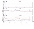
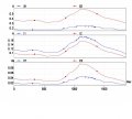
well in the attached documents you'll see the graphs.
i used a voltage divider of 100k - 1k , as the solar module was a 10W module ; Voc=21 and Isc=0.66
and a shunt 1ohm 5W

i also connected up a fixed circuit with a load of 34ohms, shunt resistor of 4.7ohms, voltage divider of 10k and 1k ;

results:

KEY
VA - voltage to ADC0 across the 10k resistor
VB - voltage to ADC1 across the 1 ohm shunt
VC - voltage across the fixed resistor divider circuit
VD - voltage across the fixed resistor shunt

X1- total voltage calculated from V = ( (R1+R2) * Va ) / R2 (mppt cct)
X2- total voltage calculated from V = ( (R1+R2) * Vc ) / R2 (fixed cct)

I1 -current calculated from I = Vb/Rshunt
I2 -current calculated from I= Vd/Rshunt

P1- power from the mppt cct X1*I1
P2 power from the fixed resistor cct X2*I2


Questions:
are microcontroller to get hot?
or maybe cos it was near a heat sink?

well it seems that the mppt is drawing current higher than the fixed resistor but the voltage is lower. any possible reasons?


THANKS!
 

Attachments

hgmjr

Joined Jan 28, 2005
9,027
hi,
.....
Questions:
are microcontroller to get hot?
or maybe cos it was near a heat sink?

well it seems that the mppt is drawing current higher than the fixed resistor but the voltage is lower. any possible reasons?


THANKS!
There is no reason why the microcontroller should be getting hot.

I'm studying the graphs and will get back with any comments or questions.

hgmjr
 

Thread Starter

olusola

Joined May 21, 2007
74
oh ok, by the way i used the interrupts version of the program.

and also is there a reason why the programmer is unable to verify what is written to the mega16?
it said something about timer and frequency but i kinda didnt take much note about it .
 
Top