RC Transmitter -- How do the controls work electrically?

Thread Starter

rhekj

Joined Sep 6, 2014
9
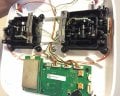
This is a DJI Phantom 2.0 drone 2.4 GHz transmitter.
Attached are a few pictures of the exterior shell of the controller and what it looks like inside of the controller.

I am trying to figure out how the joy sticks work electrically? Currently, I am thinking that there are two potentiometers for each joy stick that will control the pitch, yaw, throttle, etc. So as the user presses the joy stick more in one direction, will it supply a greater voltage to the circuit, causing the motors to increase power?

I am wondering if anyone else has better knowledge about these controllers, or any RC controller (I'm assuming that most transmitter controllers function the same way?)

So my question is, are there potentiometers underneath both of these joy sticks or is there some other way that they are functioning?

Any advice would be much appreciated.

Thank you
 

Attachments

alfacliff

Joined Dec 13, 2013
2,458
they determine the pulse output for the chanel they control. the servo also has a pot in it, attaachde to the servo shaft, the circuit tries to move the servo to the same (approximate) position as the pot in the transmitter.
 

MaxHeadRoom

Joined Jul 18, 2013
28,617
Back when we had to build our own transmitter/receivers 27Mhz a new system was developed known as digital proportional method of control, rather than a crude pulse method, I believe the latest 2.4Ghz TX,rs use the same method.
Max.
 

alfacliff

Joined Dec 13, 2013
2,458
and just like I said, each "channel" (not rf) varies its pulse according to the joystick pot for that channel.. and the servo pot provides feedback to get the motor to turn in the right direction and amount to match it. as opposed to the simple tone on/off used before.
 

alfacliff

Joined Dec 13, 2013
2,458
thats right, pwm with each pulse in a frame assigned to one channel function. for instance, the first pulse's width is determined by the throttle pot on the joystick, the second determines the postion of te rudder and such.
some of the earlier ones were real headaches, multi tone, number of times a button was pushed and that kind of thing.
 

MaxHeadRoom

Joined Jul 18, 2013
28,617
I opened one of my old Radio control annual editions, and the first line reads.

The Year 1964-65 has been an eventful year in radio control and has seen some significant changes. :cool:
Max.
 

MaxHeadRoom

Joined Jul 18, 2013
28,617
I assume one is at the pre/post transmission point, the other the transmission itself, the transmission has to include 6 channels information for the typical RC model.
Max.
 

Thread Starter

rhekj

Joined Sep 6, 2014
9
I assume one is at the pre/post transmission point, the other the transmission itself, the transmission has to include 6 channels information for the typical RC model.
Max.
Thank you!
Also would you happen to know what kind of value of resistance a potentiometer would have in a controller like this? I'm curious to know if there is a general range of appropriate resistance values that are used to operate these joysticks.
 

Thread Starter

rhekj

Joined Sep 6, 2014
9
I have never opened a current version up, but I would hazard a guess it would be in the order of 10k-15k , maximum. ?
Max.
Alright, thank you.
The reason why I ask is because I am trying to replace the mechanical input (the joysticks and potentiometers) with an electrical method (such as voltage dividers). I was hoping that by replacing a potentiometer with a voltage divider circuit, it would effectively replace the mechanical aspects with something that it completely electrical...if that makes sense.

So that is why I am trying to find out the resistance value of a potentiometer so that I could choose appropriate values for the two resistors in the voltage divider circuit.
 

Thread Starter

rhekj

Joined Sep 6, 2014
9
If you have a TX'er now, you could always measure the pot?
Max.
Yes that would have worked, but I was borrowing the Tx from someone and had to give it back intact. So that prevented us from taking apart the entire bottom part of the joystick and removing the potentiometer for measurement.
I apologize for not including this in my previous reply.
 
Top