RC Slow Rise Circuit

Thread Starter

deprove55

Joined Sep 17, 2021
15
Capture.PNG

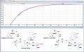
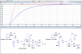
Attached is a small portion of a circuit I'm working on. The goal is to get an output, to be amplified later, that slowly rises to the setpoint (V1) over some time. V1 is also supplied from an opamp in a different part of the network. This has been working perfectly in LT Spice simulation but not on the PCB. Instead, it charges up to the setpoint within milliseconds where the simulation shows around 60 seconds until full charge. I've checked the traces and everything is connected correctly on the board so I'm thinking something here could be impacting my time constants and just isn't being considered by the LT Spice program given that all my components are ideal. Any thoughts on what's going on?
 

Attachments

Last edited:

Ian0

Joined Aug 7, 2020
9,668
What should the voltage be BEFORE it starts to rise to the set point?
Presumably, this voltage rise starts when the comparator changes state? It is a comparator with open-collector, open-drain or push-pull outputs?
 

Thread Starter

deprove55

Joined Sep 17, 2021
15
What should the voltage be BEFORE it starts to rise to the set point?
Presumably, this voltage rise starts when the comparator changes state? It is a comparator with open-collector, open-drain or push-pull outputs?
Ideally 0 but in real life it is around 0.7 because of diodes which is ok for my application.

Yes, the comparator pulls the nmos gate down to zero which enables the connection of the setpoint voltage to the RC slow rise circuit.
 

crutschow

Joined Mar 14, 2008
34,283
The simulated circuit works as expected.
It would appear that R1 and/or C1 are not the correct value on the real circuit.
What type of capacitor is C1?
 

Thread Starter

deprove55

Joined Sep 17, 2021
15
The simulated circuit works as expected.
It would appear that R1 and/or C1 are not the correct value on the real circuit.
What type of capacitor is C1?
It is an electrolytic capacitor of the same value used in the simulation.

Additionally, I double checked the capacitor and resistor values used on the board and they are the same values as shown.
 

Thread Starter

deprove55

Joined Sep 17, 2021
15
Please post a photo of your setup.
Unfortunately I cannot capture a picture of the setup without exposing the entire design which is company property. But if it helps, my comparator to nmos switching circuits are behaving as expected. To clarify what is immediately around it, The setpoint voltage is coming from an opamp configured as an amplifier. The output also goes to an opamp configured as am amplifier for fine tuning. There are no other devices connected to any nodes in this network.
 

Juhahoo

Joined Jun 3, 2019
302
how did you measure the time it takes to get fully charged?, Oscilloscope picture where you have gate voltage and RC node?
What discharges the 100uF cap ?
should be something like... 1631886855009.png
 

Ian0

Joined Aug 7, 2020
9,668
I think you’re making it complicated. Won’t this do it?01BEF953-839F-41DE-B54A-4538B827FEDF.jpeg
100Ω is to limit the current into the comparator when it switches on.
 
Top