 Facebook
 Google
 GitHub
 Linkedin
Hi all
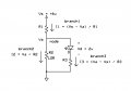
I made a simple LDR (circuit diagram below) circuit and it works. But when i do some measurements and start experimenting with the circuit i did certain observations that i would like to check with someone and see if my reasoning is correct.
1) my first resistor is a +- 266 ohm resistor dropping 4V and allowing 20Ma ... when checking the voltage in light and dark the voltage dropped over that resistor remains +- 4v and the reading on my power supply stays at 20Ma (without series resistor wit the LED) , is it correct assuming i don't need a series resistor with my LED to control the current and voltage, since this job is already done by the first resistor ? I see some change in voltage when switching between light and dark but the difference is a max of 0.7 V on the LDR.
2) the voltage drop on my LDR is 1,5V in light and 2.0V in dark (lowest = 50 ohms highest = 200.000 ohms) ... i did check the LDR in full dark and it goes up to 1 Mega ohm. Is the 0.5V change in LDR caused by the fact the normal conditions (daylight and dark) is not enough to pump up the resistance of the LDR to megaohms ... if that would be the case then i would get almost supply voltage on the LDR, correct ?
3) Even when i put a black tape over the LDR the resistance becomes 1 Megaohm . When i do the calculation r2/r1+r2 i should have VS voltage which is 6v ... when i measure it on the circuit the max voltage over the LDR remains 2V, how come ? According to the calculations i should reach full vs voltage on LDR around 200K ...
4) When i do put a series resistor before my LED (example 1 Mega ohm) i see that in light conditions the circuit draws more Mili amps then in dark conditions (in dark circuit draws +- 3 miliamps, in light +- 20 Miliamps) ... Does this mean that in light conditions (LDR at lowest) the 20Ma goes directly through the LDR and in light the the 1megaohm series resistor limits the total circuit current and only 3Ma is the available current ?
5) The equivalent resistance with 2 resistors in parralel is lower then the smallest resistance. So by adding the 1 megaohm resistor in parralel to the LDR, is it correct that my Total resistance in the whole circuit does not change much (because the lowest resistance is 50 ohms of the LDR). it only influances the voltage and current in the branch of the LED ,however i do see that in that case in light or dark almost full supply voltage is dropped over the LDR propably caused by the fact that de resistance in LED branch is so high thats the current chooses the LDR path, correct ?
Thx for the help
Mike
Attachments
-
 32.4 KB Views: 22


