Question regarding step response of Butterworth filter

Thread Starter

rughooam

Joined Feb 1, 2018
5
Hi,
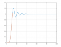
I am currently looking into a low pass filter with very small propagation delay. I designed a Butterworth filter in matlab and I have attached the step response to this thread. Matlab indicate that the settling time is about 19us. I drew a line at 19us and then traced it back to where the amplitude match the final amplitude at settling time.

Is there any reason I cannot wait only the 4us and sample the output there. Does that amplitude point changes based on freq or start and end amplitude of filter input. Any insight would be highly appreciated
 

Attachments

crutschow

Joined Mar 14, 2008
34,408
If you sample before the filter has settled, then you are depending upon the filter time-constants staying constant, and ignoring the tolerance of the filter elements.
How are you going to select this time to sample -- theoretically, or measurements from the built filter?

But as long as you are in the linear region of the filter, the risetime and sample point will not change with signal amplitude.

I suggest using a filter with a smaller overshoot (Bessel) or no overshoot (Gaussian).
Here's the simulation of an example 3-pole active filter with no overshoot.

upload_2018-4-3_13-52-22.png
 

Papabravo

Joined Feb 24, 2006
21,225
An Impertinent question: why did you select a Butterworth Filter? If your requirement was a fast, overdamped, step response -- it is manifestly the wrong choice for that requirement. It's only redeeming characteristic is that the magnitude response is FLAT in the passband: by design. Every other design has similar compromises.
 

Thread Starter

rughooam

Joined Feb 1, 2018
5
If you sample before the filter has settled, then you are depending upon the filter time-constants staying constant, and ignoring the tolerance of the filter elements.
How are you going to select this time to sample -- theoretically, or measurements from the built filter?

But as long as you are in the linear region of the filter, the risetime and sample point will not change with signal amplitude.

I suggest using a filter with a smaller overshoot (Bessel) or no overshoot (Gaussian).
Here's the simulation of an example 3-pole active filter with no overshoot.

View attachment 149711
The filter is digital so it would be built using an FPGA. The tolerance is pretty tight for the FPGA internals as long as voltage and temp is stable.
Using a small overshoot filter provides a long propagation delay. In your example, around 6us. That is too much for our design.
 

Thread Starter

rughooam

Joined Feb 1, 2018
5
An Impertinent question: why did you select a Butterworth Filter? If your requirement was a fast, overdamped, step response -- it is manifestly the wrong choice for that requirement. It's only redeeming characteristic is that the magnitude response is FLAT in the passband: by design. Every other design has similar compromises.
Since we will be implementing this digitally in an FPGA, we are severely constrained to the number of second order section we can put in. This is the main reason not to choose a more complex filter. Also we need the passband to be very flat.
 

crutschow

Joined Mar 14, 2008
34,408
Then if it's a digital filter you should be able to accurately pick a point on the rise to sample the signal, within the time and amplitude resolution of the digital sample word.
 

mlv

Joined Nov 6, 2017
17
I presume that your filter is being applied to a signal that is semi-static and that you want to sample the filtered semi-static signal after the filter has settled following a level change in the semi-static signal.

If this is done at the early point of the step response, the effective filter is different than the underlying filter, and you will not benefit from the intended response. For the noise-free, step-response case, this is fine. The question for you to evaluate is whether you need the Butterworth response or not.

I'll demonstrate below with a Matlab example session. Start with a Butterworth filter design and plot the step response:
>> [b, a] = butter(11,0.25);
>> plot(filter(b,a,[ones(100,1)]))
>> grid

The step response settles at 1 and first crosses 1 around sample 12 (slight overshoot at sample 12). If we want to sample our filter output at this time offset rather than let it settle further after a step change, we are essentially only using these first 12 samples of the impulse response for filtering. It is as though we define an FIR of 12 taps rather than the 11th order IIR Butterworth and letting it settle:
>> h = filter(b,a,ones(12,1));
>> hold on
>> plot(h)
upload_2018-4-6_23-51-4.png
The next question is: what is the frequency response of this FIR filter 'h' and how does it compare to the frequency response of the underlying Butterworth?
>> H = freqz(b,a,8192);
>> Hh = freqz(h,1,8192);
>> figure
>> plot(abs(H))
>> hold on
>> plot(abs(Hh/sum(h)))

(I needed to scale the FIR response to match gains at DC.)

upload_2018-4-6_23-51-33.png

Cheers,
M.
 

Attachments

mlv

Joined Nov 6, 2017
17
Sorry - I tried to edit the above after posting but missed the 10 min window. I made the mistake of taking the first 12 samples of the *step* response for the FIR filter 'h' in the post above. I should have computed the first 12 taps of the *impulse* response as the effective FIR filter and plotted its frequency response for comparison to H:
>> himp = filter(b,a,[1;zeros(11,1)]);
>> Hh = freqz(himp,1,8192);
>> plot(abs(H))
>> hold
>> plot(abs(Hh/sum(himp)))
upload_2018-4-7_0-6-14.png

...nearly the same. Sorry for the confusion.
 

Thread Starter

rughooam

Joined Feb 1, 2018
5
Sorry - I tried to edit the above after posting but missed the 10 min window. I made the mistake of taking the first 12 samples of the *step* response for the FIR filter 'h' in the post above. I should have computed the first 12 taps of the *impulse* response as the effective FIR filter and plotted its frequency response for comparison to H:
>> himp = filter(b,a,[1;zeros(11,1)]);
>> Hh = freqz(himp,1,8192);
>> plot(abs(H))
>> hold
>> plot(abs(Hh/sum(himp)))
View attachment 149927
Interesting. I will need to look at this more thoroughly monday but clearly the freq response is greatly affected. That actually is a big issue in my application. We need the gain in the passband to be flat. Thanks a lot for this insight.
...nearly the same. Sorry for the confusion.
 
Top