Facebook
 Google
 GitHub
 Linkedin
First off, I know there has been discussion on flasher circuits for high power LEDs, and it is something I have been working on for awhile (with a couple of previous posts on this forum looking for help). I shelved the project for awhile because I simply got too frustrated with it. I went back to it today, and I have some questions. NOW I am NOT looking for a solution, per se, but the education/knowledge as to WHY I can or can't do things certain ways. So let me start with a general synopsis of my experience so far, and maybe a few of you can answer some of my general questions?
In my first attempt, I wanted to do something based around an LM555 like such:

I understand that this works for standard LEDs becuase they don't draw a large amount of current like high-power LEDs. The 555 can only handle a max of 200mA I believe. So when I look at the spec sheets for the LEDs I am using (which are THIS and
THIS I would need it to be able to hand 350-400mA on the RGB (color-dependent) and 750mA on the white. So, this solution doesn't work simply because the 555 can't handle it, correct?
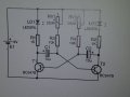
The second solution I looked at would be something like this:
So, I built one of these with some spare parts and low-power 20mA red standard LEDs and it worked well. So out of curiosity, I hooked in the high-power LEDs (subbing in the appropriate resistors instead of the 470Ω) and it worked. But I noticed the flash rate went WAY up. I thought about it, and presumably this is because the higher current-draw was draining the capacitors faster. So, I opted for high value caps and tried some 100μf and 47μf values just to see what would happen. As predicted, the 100μf caps slowed the flash rate considerably, too slow for what I wanted, but the 47's did the trick. So all seemed to be well, it seemed as though I had everything figured out.
Next day, I hooked the circuit back up again to continue working on it, and wanted to try something more. I built 2 of the "fast" (47μf cap) circuits and a "slow" (100μf cap) circuits each on their own mini perfboards so that I could see if connecting the fast ones to each "output" of the "slow" one would work as expected - flash two LEDs quickly on one side on the slow board, then the other two LEDs quickly on the other. This lead to some interesting results. The LEDs flashed, but in a seemingly random pattern that was all over the place. Why would this be? Is it just that the drain on the caps isn't consistent enough to keep the flash rate consistent?
Final question: when I went back to the project the next day, now NONE of the circuits seem to flash the high power LEDs anymore... they will still work with low power LEDs, though, so I don't think I "fried" anything (like the transistors or caps), but basically, no matter which circuits I use the LEDs just all light up simultaneously. At this point, I have become frustrated and am ready to shelve the project again - i just can't seem to wrap my head around any of this. I am new to the whole idea of building my own electronics. I am quite capable when it comes to taking a schematic and building it, and my soldering skills are decent enough to not be making lots of bad connections or anything, but when it comes to reading about MOSFETs and PuckBucks and the difference between an NPN and a PNP transistor with sinking and sourcing currents, my head begins to spin.
Can anyone help me out and try to set me straight here? Am I just going down a never ending road of projects I should never have started?
In my first attempt, I wanted to do something based around an LM555 like such:
I understand that this works for standard LEDs becuase they don't draw a large amount of current like high-power LEDs. The 555 can only handle a max of 200mA I believe. So when I look at the spec sheets for the LEDs I am using (which are THIS and
THIS I would need it to be able to hand 350-400mA on the RGB (color-dependent) and 750mA on the white. So, this solution doesn't work simply because the 555 can't handle it, correct?
The second solution I looked at would be something like this:
So, I built one of these with some spare parts and low-power 20mA red standard LEDs and it worked well. So out of curiosity, I hooked in the high-power LEDs (subbing in the appropriate resistors instead of the 470Ω) and it worked. But I noticed the flash rate went WAY up. I thought about it, and presumably this is because the higher current-draw was draining the capacitors faster. So, I opted for high value caps and tried some 100μf and 47μf values just to see what would happen. As predicted, the 100μf caps slowed the flash rate considerably, too slow for what I wanted, but the 47's did the trick. So all seemed to be well, it seemed as though I had everything figured out.
Next day, I hooked the circuit back up again to continue working on it, and wanted to try something more. I built 2 of the "fast" (47μf cap) circuits and a "slow" (100μf cap) circuits each on their own mini perfboards so that I could see if connecting the fast ones to each "output" of the "slow" one would work as expected - flash two LEDs quickly on one side on the slow board, then the other two LEDs quickly on the other. This lead to some interesting results. The LEDs flashed, but in a seemingly random pattern that was all over the place. Why would this be? Is it just that the drain on the caps isn't consistent enough to keep the flash rate consistent?
Final question: when I went back to the project the next day, now NONE of the circuits seem to flash the high power LEDs anymore... they will still work with low power LEDs, though, so I don't think I "fried" anything (like the transistors or caps), but basically, no matter which circuits I use the LEDs just all light up simultaneously. At this point, I have become frustrated and am ready to shelve the project again - i just can't seem to wrap my head around any of this. I am new to the whole idea of building my own electronics. I am quite capable when it comes to taking a schematic and building it, and my soldering skills are decent enough to not be making lots of bad connections or anything, but when it comes to reading about MOSFETs and PuckBucks and the difference between an NPN and a PNP transistor with sinking and sourcing currents, my head begins to spin.
Can anyone help me out and try to set me straight here? Am I just going down a never ending road of projects I should never have started?