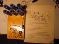
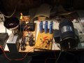
PWM pump driver, needs feeback to slow pump when supply current falls from PV (with pixs, schematic)

ronv

Joined Nov 12, 2008
3,770
I have NOS of the BP275, with an oc voltage of about 21.0

In looking thru my box of electrolytics, it seems I may have use caps in series, with balancing resistors.
I do have many unmatched 220 to 450v caps, and that is also an option.

I'm a little rusty: if I place two 75v 2000uf caps in series, then I increase the voltage handling, and decrease the
total capacitance, yes or no? So, in the above example = 150v & 1000uf?
It would be helpful to know the planned voltage and the stalled voltage of the motor.
If we had that we could choose some adjustment points so you don't have to redo things at the end.
My vote would be for multiple caps in parallel as when it is putting along the current they need to supply will be large, so more is probably better.
But yes, your thinking is correct.
 

Thread Starter

Hamlet

Joined Jun 10, 2015
560
5x panels @17v MPP = 85v. That's what I'm going to shoot for. I have ten panels, in crates, so I can add one if needed.

The pump probably won't stall until I hit 30v or so. I've found some time, so I am working on it today. I have it wired
up on my ole' plywood. I am building an isolated 90v power supply with current control for testing. Then I have to
set the motor/pump on the workbench, fix a supply line, and discharge with valve and gauge to simulate 55feet of head...
But first I need to discover if the motor will turn :)


DSCF3208x.JPG
 

Bernard

Joined Aug 7, 2008
5,784
You may wish to replace R5 with a pot. maybe around 200k to 500k in series with a 47k. As shown , the trip point is about 46 V so there will not be much energy in cap. bank. Experimentation with SP- cap. & motor will tell.
 

Thread Starter

Hamlet

Joined Jun 10, 2015
560
You may wish to replace R5 with a pot. maybe around 200k to 500k in series with a 47k. As shown , the trip point is about 46 V so there will not be much energy in cap. bank. Experimentation with SP- cap. & motor will tell.
Thanks, I may try that. I finally finished my set up, and what I found was inconclusive. At least I didn't release any smoke.
Motor runs fine, either with, or without the device. With the current boost device, the motor stalls about 49v, drawing 1.4A, and the same without, but this is with the large heat lamp as a current limiter. I removed the capacitor bank from the pwm, and I couldn't detect a difference.

For my testing power supply (on the right) I'm using a large transformer, a inductive rated dimmer, a few caps, and a large 250w what light bulb to limit current.

DSCF3210 PWM.JPG

I don't know what to try next. Either a better power supply, or a scope.
 

ronv

Joined Nov 12, 2008
3,770
Thanks, I may try that. I finally finished my set up, and what I found was inconclusive. At least I didn't release any smoke.
Motor runs fine, either with, or without the device. With the current boost device, the motor stalls about 49v, drawing 1.4A, and the same without, but this is with the large heat lamp as a current limiter. I removed the capacitor bank from the pwm, and I couldn't detect a difference.

For my testing power supply (on the right) I'm using a large transformer, a inductive rated dimmer, a few caps, and a large 250w what light bulb to limit current.

View attachment 118308

I don't know what to try next. Either a better power supply, or a scope.
We might just need to chase the stall voltage around a little.:D
See if you can change r5 to 130K and R7 to 200k or so. That should make it turn off the motor before it stalls at about 54 volts and back on at about 60 volts.
If that doesn't do it measure the voltage at the + and - inputs at some set voltage, say 60 volts.
 

Thread Starter

Hamlet

Joined Jun 10, 2015
560
We might just need to chase the stall voltage around a little.:D
See if you can change r5 to 130K and R7 to 200k or so. That should make it turn off the motor before it stalls at about 54 volts and back on at about 60 volts.
If that doesn't do it measure the voltage at the + and - inputs at some set voltage, say 60 volts.
;) I added 33K to R5 for a total of 133k, and replaced r7 with 200k. It cogs like a stepper motor, about 30rpm @ 60v.
I think we're going the right direction! When I get go back up to 64v, it smooths out again. (I am not current-limiting the
transformer in my power supply.) I might add that nothing gets hot, with the exception of R1.
 

Thread Starter

Hamlet

Joined Jun 10, 2015
560
With only power supply, cap. C, bank, & motor, try charging C to various V's 7 discharging C into the motor.
What is the lowest V that will run motor for a few revolutions. When charged to 90 V will motor do any usefull work?
Might like to read about a similar project from 2009, http://www.voltscommissar.net/minimax/minimax.htm
Thank you, excellent link! I have yet to determine if the motor will be able to do any work. For now, I can grab the shaft with a gloved hand
at lower voltages, or rub a hole in my shoe, but I need to get my pump mated to the shaft to determine how much pressure I can develop.
 

dannyf

Joined Sep 13, 2015
2,197
and I couldn't detect a difference.
That's to be expected as pointed out earlier.

Your issue isn't that the panels cannot crank out enough voltage. It is that the panels cannot crank out enough current to drive the motor.

What the commercial product quoted earlier did is to trade voltage for current so it can still drive the motor at lower voltage.
 

ronv

Joined Nov 12, 2008
3,770
;) I added 33K to R5 for a total of 133k, and replaced r7 with 200k. It cogs like a stepper motor, about 30rpm @ 60v.
I think we're going the right direction! When I get go back up to 64v, it smooths out again. (I am not current-limiting the
transformer in my power supply.) I might add that nothing gets hot, with the exception of R1.
I think you have it!:D What we need is a constant current supply like your solar panels. The lamp should kind of do that. Can you measure the voltage before and after the lamp?
Edit:
Yes, R1 wants to be about 5 watts.
 
Last edited:

Thread Starter

Hamlet

Joined Jun 10, 2015
560
I think you have it!:D What we need is a constant current supply like your solar panels. The lamp should kind of do that. Can you measure the voltage before and after the lamp?
It is difficult to measure. I have the lamp placed on the mains side of the transformer. Perhaps
I should move it to the output side, before the the bridge.

PWM power supply.png
 

Thread Starter

Hamlet

Joined Jun 10, 2015
560
Probably doesn't make much difference. Maybe you can just measure the output voltage with and without the motor.
I moved the bulb to the output side of the transformer, before the rectifier. It makes little difference.

I think my power supply is too spongy. With a link placed where the bulb should go, and then set the dimmer so
I am seeing 90v at the motor itself, and then when I remove the motor, I get 112v. Placing the bulb in the circuit
really drags the voltage down, the motor cogs, and I can't get a reading, so I have to lift the slide on my dimmer
to jack up the voltage. I think my dimmer is adding some variable that I can't sort out. Maybe I should remove the
dimmer, add a few more wraps to my primary, and shoot for a rectified voltage of 95v or so... (edit: disclosure, my isolation transformer was an auto-trans rated at 3kw, which I rewired as an isolated secondary. No way was it ever 3kw, and certainly not after converting it to an isolation transformer. It uses only 14g wire.)

I have to say, it cogs at what seems to be very little amperage, but when it cogs this slowly, my DVM can't
really take a reading when I try to measure amps. If I elevate it 2 or 3 volts, just until it smooths out, and I see about
.56A draw.

Ahem.

Question: Can I replace R5 & R6 with a resister/pot/resistor, for matching purposes? 30k/100k-pot/15k??

Question: Replace R7 with 200k pot? Maybe I can discern where my transitions are if I can lower
this value to induce a little "chatter"?
 
Last edited:

ronv

Joined Nov 12, 2008
3,770
I moved the bulb to the output side of the transformer, before the rectifier. It makes little difference.

I think my power supply is too spongy. With a link placed where the bulb should go, and then set the dimmer so
I am seeing 90v at the motor itself, and then when I remove the motor, I get 112v. Placing the bulb in the circuit
really drags the voltage down, the motor cogs, and I can't get a reading, so I have to lift the slide on my dimmer
to jack up the voltage. I think my dimmer is adding some variable that I can't sort out. Maybe I should remove the
dimmer, add a few more wraps to my primary, and shoot for a rectified voltage of 95v or so... (edit: disclosure, my isolation transformer was an auto-trans rated at 3kw, which I rewired as an isolated secondary. No way was it ever 3kw, and certainly not after converting it to an isolation transformer. It uses only 14g wire.)

I have to say, it cogs at what seems to be very little amperage, but when it cogs this slowly, my DVM can't
really take a reading when I try to measure amps. If I elevate it 2 or 3 volts, just until it smooths out, and I see about
.56A draw.

Ahem.

Question: Can I replace R5 & R6 with a resister/pot/resistor, for matching purposes? 30k/100k-pot/15k??

Question: Replace R7 with 200k pot? Maybe I can discern where my transitions are if I can lower
this value to induce a little "chatter"?
Sure, maybe 100k pots in series with what was there.
 

Thread Starter

Hamlet

Joined Jun 10, 2015
560
I'm going to post my notes as I work on development of this circuit. No replies are
necessary, but if anybody would like to chime in, I welcome your input. Big thanks
to all of you that have helped the progress thus far, especially a big high five to Ron V
for his patience! :)

For grins, I replaced the 3000uF (the blue, six cap bank in the picture) with a 470uF cap.
The motor cogs as low as 2.5volts as measured at the motor, & a 20v it is starting to smooth,
with appreciable torque. Seems counter-intuitive, so I thought I would share.
(EDIT: those voltage readings were anomalous. Disregard. The cap test is still valid.)
 
Last edited:

ronv

Joined Nov 12, 2008
3,770
I moved the bulb to the output side of the transformer, before the rectifier. It makes little difference.

I think my power supply is too spongy. With a link placed where the bulb should go, and then set the dimmer so
I am seeing 90v at the motor itself, and then when I remove the motor, I get 112v. Placing the bulb in the circuit
really drags the voltage down, the motor cogs, and I can't get a reading, so I have to lift the slide on my dimmer
to jack up the voltage. I think my dimmer is adding some variable that I can't sort out. Maybe I should remove the
dimmer, add a few more wraps to my primary, and shoot for a rectified voltage of 95v or so... (edit: disclosure, my isolation transformer was an auto-trans rated at 3kw, which I rewired as an isolated secondary. No way was it ever 3kw, and certainly not after converting it to an isolation transformer. It uses only 14g wire.)

I have to say, it cogs at what seems to be very little amperage, but when it cogs this slowly, my DVM can't
really take a reading when I try to measure amps. If I elevate it 2 or 3 volts, just until it smooths out, and I see about
.56A draw.

Ahem.

Question: Can I replace R5 & R6 with a resister/pot/resistor, for matching purposes? 30k/100k-pot/15k??

Question: Replace R7 with 200k pot? Maybe I can discern where my transitions are if I can lower
this value to induce a little "chatter"?
Maybe the sag in your power supply is okay. That's kind of what will happen to your panel as the sun goes down. Do you have any real big low value resistors?
 

Thread Starter

Hamlet

Joined Jun 10, 2015
560
Maybe the sag in your power supply is okay. That's kind of what will happen to your panel as the sun goes down. Do you have any real big low value resistors?
As it were, I've been stockpiling cement power resistors, and thought I had enough...
Mostly 5w & 10w though... a few 25w, mostly bunches of .1, .5, 1, 2.2, 5, 10 ohm.
What's your idea?
 

ronv

Joined Nov 12, 2008
3,770
As it were, I've been stockpiling cement power resistors, and thought I had enough...
Mostly 5w & 10w though... a few 25w, mostly bunches of .1, .5, 1, 2.2, 5, 10 ohm.
What's your idea?
I sense it is not working the way you think it should or I don't understand how it works, so I'm searching for a way to better demonstrate it. But maybe some more words will work. Here is what I think it does:
The curves for the solar panel look like this:

So even in low light the voltage will go to almost the same maximum level.
But at some point it won't be able to supply enough current to run the pump.
But, if you turn off the motor the capacitors will eventually charge up to the higher voltage.
If you then turn the motor on the capacitors will supply the needed current for a short period of time - like a small battery that quickly goes dead.
The advantage is that even though the panels can't supply enough current to run the motor anymore it will still chirp along with the circuit.
So what I was thinking of is adding some resistance in series to the circuit to make the power supply look more like a voltage supply. Lets say you put in 2 10 ohm resistors and set the voltage to 75 or 80 volts simulating maximum solar voltage. when the motor is running the voltage will drop to about 55 or 60 volts like a panel under load. You could then adjust the voltage until it pulsed. If you remove the circuit the motor won't run. And if you jumper out one resistor (like the sun came back out) it will run smooth.
Or did I misread your concerns?:D
 

Thread Starter

Hamlet

Joined Jun 10, 2015
560
I sense it is not working the way you think it should or I don't understand how it works, so I'm searching for a way to better demonstrate it. But maybe some more words will work:D
I am satisfied with the way it works, I am much impressed, and grateful for your assistance.
Your description of operation appears correct. At the lower range of available current, the motor
will only turn over with the device in place. It is an elegant design.

What might be nice is if you can offer a hint as to where to place an LED or
some other kind of detection device that would indicate when the device's
MOSFET is switching, sending pulses of energy to the motor. I can detect
this visually at very low currents, obviously, because the motor is cogging.
But when the motor smooths out, and up the the transition to full on, is
what I would like to detect.
 

Bernard

Joined Aug 7, 2008
5,784
R1 should be able to supply 5 mA for a LED without disturbing the circuit. If ronv concurs, might connect U1 output to the base of an emitter follower like a 2N3904, collector to +12V, & emitter to 2k, other end to LED anode, cathode to ground.
 
Top