PWM pump driver, needs feeback to slow pump when supply current falls from PV (with pixs, schematic)

Thread Starter

Hamlet

Joined Jun 10, 2015
560
I've been working with Wendy's PWM circuit on the bench, and so far, so good.
I anticipate driving a pump from PV, but when clouds or haze reduce available current,
the pump is going to stall. I need some kind of feedback from the supply side, that
tells the PWM to narrow the pulse-width when the panels can't deliver full current
do to passing clouds, early morning or late afternoon, etc.

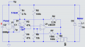
This is the schematic that I am working with, I added a zener at the gate, and the LED array
is replace with a motor, with a freewheel diode:


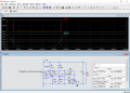
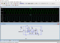
And this is my bench reference design:
Wendy\'s PWM refernce design in metal & wood.JPG

Works nicely, up to 5A without a heatsink on the mosfet. 555 on the left, LM393 on right.
Old school breadboard handles more current, and makes testing & tweaking easier. I can
shrink later it to a pcb when I get the bugs worked out.

If I could automate the PWM signal with this design, that would be great.
 

crutschow

Joined Mar 14, 2008
38,418
You could try connecting the PV voltage to R4 in place of Vcc to vary the PWM duty-cycle with that voltage (I think you may have to invert the inputs to U2-A to get the proper change in duty-cycle with voltage).

But I'm not sure that changing the duty-cycle will prevent the motor from stalling.
Have you tried it to see if it actually helps?

It's been a long time since I've seen a breadboard circuit that's literally done on a wooden board. :)
 

Thread Starter

Hamlet

Joined Jun 10, 2015
560
Let me note that I am desiring a grid/battery-free design.
Pumping water without batteries in a PV system is common
with airriating pond fountains, irrigation, filling stock tanks, etc.

I live in the PacNW, so lots of clouds and overcast. I don't want
to manually have to dial-down my pump when the PV output
current falls. I'd loose much capacity if it were direct drive, or
my PV array would have to be ten times larger.

Devices are available commercially, but they get expensive fast.

https://www.altestore.com/store/solar-water-pumps/linear-current-boosters-for-solar-pumps-c581/

I want to own my systems, not rent someone else's designs.
 

ronv

Joined Nov 12, 2008
3,770
Let me note that I am desiring a grid/battery-free design.
Pumping water without batteries in a PV system is common
with airriating pond fountains, irrigation, filling stock tanks, etc.

I live in the PacNW, so lots of clouds and overcast. I don't want
to manually have to dial-down my pump when the PV output
current falls. I'd loose much capacity if it were direct drive, or
my PV array would have to be ten times larger.

Devices are available commercially, but they get expensive fast.

https://www.altestore.com/store/solar-water-pumps/linear-current-boosters-for-solar-pumps-c581/

I want to own my systems, not rent someone else's designs.
You have 1/2 339 left so you could make a low voltage cutoff out of it and shut off the PWM.
I can play with something if you like. What voltage does the motor stall at?
 

Thread Starter

Hamlet

Joined Jun 10, 2015
560
@Hamlet One more question...
Why do you need the pwm? Why not just run the pump as fast as the panel will allow?
Good question, Ron! I suppose I am imagining a cap bank charging up between pulses, then
when the fet switches on, the motor gets a good whack of juice to get started & this should keep the pump motor
running longer in the late afternoon, or cloudy periods.

I have a small stockpile of mostly new pumps, motors, etc, most are captive displacement pumps,
and the motors are 12v, 24, 90v, and 110v DC. I run #2 wire to my well & the ac pump that I'm currently using, about
1/4 mile distant. What I envision is using my 90v/3A DC motor, as to avoid too much voltage drop. I figure 5x series
75w panels dedicated to the project, pumping into a 10k gallon storage near the house and barn. I can
pressurize it for domestic use after the tank.
 

dannyf

Joined Sep 13, 2015
2,197
This is the schematic that I am working with
The 555 is totally unnecessary - it can be replaced with the other half of the 393/comparator/opamp.

that
tells the PWM to narrow the pulse-width when the panels can't deliver full current
do to passing clouds
you can implement that via a summing circuit (=a resistor) to Vcc on the non-inverting pin of the comparator.

But I don't think it fundamentally changes the picture for you.
 

ronv

Joined Nov 12, 2008
3,770
Good question, Ron! I suppose I am imagining a cap bank charging up between pulses, then
when the fet switches on, the motor gets a good whack of juice to get started & this should keep the pump motor
running longer in the late afternoon, or cloudy periods.

I have a small stockpile of mostly new pumps, motors, etc, most are captive displacement pumps,
and the motors are 12v, 24, 90v, and 110v DC. I run #2 wire to my well & the ac pump that I'm currently using, about
1/4 mile distant. What I envision is using my 90v/3A DC motor, as to avoid too much voltage drop. I figure 5x series
75w panels dedicated to the project, pumping into a 10k gallon storage near the house and barn. I can
pressurize it for domestic use after the tank.
Five 12 volt panels?
I know you have a lot of work in it, but I think I would skip the PWM and just turn off the pump when the voltage is to low for it to keep running. Maybe something like this:
 

Attachments

Thread Starter

Hamlet

Joined Jun 10, 2015
560
Five 12 volt panels?
I know you have a lot of work in it, but I think I would skip the PWM and just turn off the pump when the voltage is to low for it to keep running. Maybe something like this:
Thank you. No, I don't mind taking a new direction. I've learned a lot fooling with the PWM circuits. I now have one in DIY my soldering station.
As I understand it, the situation is so much disconection when the volts drop, but a means to get the pump started, and maintaining a modest output, even in cloudy weather. Better to have a trickle, than bone dry, as it were

I don't have the time to study your circuit at the moment, Ron, but I will, as best as I can, in the morning. Let me leave two links of interest,
one is for commercial units, an the other is a homebrew from some fellow doing something simular, here's his schematic:


http://www.radanpro.com/Radan2400/MotorAndControl/Pump Controller or LCB.htm

I don't know why my text turned green... anyway, here is a link for commercial units:

https://www.altestore.com/store/solar-water-pumps/linear-current-boosters-for-solar-pumps-c581/
 

ronv

Joined Nov 12, 2008
3,770
Thank you. No, I don't mind taking a new direction. I've learned a lot fooling with the PWM circuits. I now have one in DIY my soldering station.
As I understand it, the situation is so much disconection when the volts drop, but a means to get the pump started, and maintaining a modest output, even in cloudy weather. Better to have a trickle, than bone dry, as it were

I don't have the time to study your circuit at the moment, Ron, but I will, as best as I can, in the morning. Let me leave two links of interest,
one is for commercial units, an the other is a homebrew from some fellow doing something simular, here's his schematic:


http://www.radanpro.com/Radan2400/MotorAndControl/Pump Controller or LCB.htm

I don't know why my text turned green... anyway, here is a link for commercial units:

https://www.altestore.com/store/solar-water-pumps/linear-current-boosters-for-solar-pumps-c581/

Yep, I see now.
The good news is that's pretty much what the circuit I posted does. The thing that is missing is some big capacitors to act like little batteries. So If you add some capacitance in parallel with the panel it should work. It's going to take some experimenting to match it to your motor & panel. So we would need to add some adjustments.
Here is how it works.
D1 is a 12 volt zener diode to make a little 12 volt power supply to run the 339 and drive the FET
R3 & R4 divide this in half to form a reference for the 339.
R5 & R6 divide the 90 volts down to around the reference voltage.
So if the + input (90V) is above the reference the FET is turned on to drive the motor.
If it falls below the reference it turns the FET off.
R7 makes the two transitions a few volts different so it doesn't chatter around the reference.
So lets say the panel can only put out 1 amp instead of 3 because there is not enough sun.
The large caps across the panel they will charge up until the voltage turns on the FET. The motor current will discharge the caps until the voltage falls below the reference. This will repeat just like a PWM.
Do you own a scope?
 

Attachments

dannyf

Joined Sep 13, 2015
2,197
As I understand it, the situation is so much disconection when the volts drop, but a means to get the pump started, and maintaining a modest output, even in cloudy weather.
the "current booster" looks to be a buck converter -> it steps down the output from the solar panel to the lowest voltage that can still run the motor, in that process, it "boosts" the current.

figure out how much lower your pump can run and a dc/dc converter to that voltage will do the trick.

a typical solder station can be easily diy'd with a mcu + laptop power supply. I have done countless of those.
 

Thread Starter

Hamlet

Joined Jun 10, 2015
560
Thanks! No, I don't have a scope. I don't know whether to get a toy like the lcd ones from china/ebay,
or get something more professional.

I can follow your notes well enough, but the schematic is hard for my eyes. Can you post
a larger one? Also, what is the value for L1? I might need to order that, but I do have
the caps. Is layout critical? I think I will protype it on wood.
 

Thread Starter

Hamlet

Joined Jun 10, 2015
560
the "current booster" looks to be a buck converter -> it steps down the output from the solar panel to the lowest voltage that can still run the motor, in that process, it "boosts" the current.

figure out how much lower your pump can run and a dc/dc converter to that voltage will do the trick.

a typical solder station can be easily diy'd with a mcu + laptop power supply. I have done countless of those.
Thanks Danny. I have considered this, but not sure how it would work in practice. I bet these motors would pump as low as 48v,
as I had one working from grid power at 60v, pushing 100psi, although the amp draw was somewhat over rated at that pressure.
 

ronv

Joined Nov 12, 2008
3,770
Thanks Danny. I have considered this, but not sure how it would work in practice. I bet these motors would pump as low as 48v,
as I had one working from grid power at 60v, pushing 100psi, although the amp draw was somewhat over rated at that pressure.
Let's try this one.
One of the keys to this is the capacitors that I added (see red arrow)
The more or the larger the better the chance the motor will start at low voltage/current.
PS.
Should be okay on bread board.
It may be a little hard on the motor as it will keep trying to start, but maybe not so bad.
PSS
L1 is just how I showed the motor in the simulation.
 

Attachments

Thread Starter

Hamlet

Joined Jun 10, 2015
560
Let's try this one.
Should be okay on bread board.
Ah, a much clearer schematic, thank you! Okay, I'll try to whip something
up on a breadboard. It might take a day or two, as my wife has some chores
for me.
 

drc_567

Joined Dec 29, 2008
1,156
A little clarification ... you are going to use a quarter mile length of #2 wire to power a DC pump motor?
...Does that include the ground wire?
Resistance = .41 ohms * 2
power loss = I^2*R = 10 watts or so
 
Last edited:

Thread Starter

Hamlet

Joined Jun 10, 2015
560
A little clarification ... you are going to use a quarter mile length of #2 wire to power a DC pump motor?
...Does that include the ground wire?
Resistance = .41 ohms * 2
power loss = I^2*R = 10 watts or so
1100 feet times three wires. #2, Al. The max load may be about 250w, maybe a lot less, as I won't be pressurizing.
 

Thread Starter

Hamlet

Joined Jun 10, 2015
560
Voltage rating of C2 should be at least open circuit V of solar panel bank, maybe around 106 V ?
I have NOS of the BP275, with an oc voltage of about 21.0

In looking thru my box of electrolytics, it seems I may have use caps in series, with balancing resistors.
I do have many unmatched 220 to 450v caps, and that is also an option.

I'm a little rusty: if I place two 75v 2000uf caps in series, then I increase the voltage handling, and decrease the
total capacitance, yes or no? So, in the above example = 150v & 1000uf?
 
Last edited:
Top