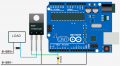
The MOSFET shown in your second picture is a P channel MOSFET which usually is used to switch the high side. You have it on the low side. It also must be a logic level MOSFET as the Arduino GPIO can only provide 5V (at most). Just because you can power the Arduino with 12V doesn’t mean you can connect 12V devices to it (without driver circuitry). The 12V input goes through an onboard voltage regulator, bringing the MCU voltage down to 5V. Your diagram is missing a lot of information and likely won’t work.
The P channel Mosfet used can take +-20 Volts through the gate & can be used as a switch via this method.
An Arduino if powered through certain pins can entirerly bypass the 5V regulator.
The P channel Mosfet used can take +-20 Volts through the gate & can be used as a switch via this method.
An Arduino if powered through certain pins can entirerly bypass the 5V regulator.
Pin 6 & 5V output as can be seen in the picture are the connection points . . . The voltage applied to the 5 volt output pin brings pin 6 into a open circuit state at the applied voltage without interferring the MCU.
Pins 5,6 & 7 go to the LM358 to be able to recieve tiny inputs then amplify them to be processed by the MCU. digital signals.
By knowing the characteristics of the LM358 that has 2 internal bipolar transistors & has -+16 volt threshold it is possible to send it into reverse avalanche mode by using the Arduino's 5 volt with the 12 volt already being applied.
This is also what happens to the IRF9540n transistor which has a 9 Volt threshold at the gate/base.
I thought you both would have known this as there is no way to make an Arduino go into a negitive voltage range. There is only high +5V or low +-0 & as I have only a positive feed going into the Arduino it make a negitive voltage impossible.
It is a common misconception that power runs from positive to negitive when it is actually the opposite.
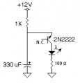
Here is the same principle for flashing a led using just 2 pins on a 2n2222 transistor in reverse avalanche mode & of course the rate can be changed by the component sizes.
I only used the components sharanvshnu had shown is his diagram but if I had to make this circuit myself I would do it something like this,
I hope we all remember what this thread was actually about.
hi PRASS,
The TS posted a Thread asking why his circuit does not work as expected.
He now has the P MOSFET correctly wired, so the hardware side is OK.
The problem LED current he is measuring, maybe due to the way he is driving the MOS Gate from his Arduino.
If he tries the simple test I suggested, in shorting the 2N2222 transistor Collector to 0V, it should turn the FET hard ON, then measure the LED current and post back what he finds. It should be close to 280mA.
Regarding the Quote: He is not asking for someone to design a new circuit, I know that's tempting to do, but it will not really help him understand why his version of the circuit does not work,,, ie: learning why.
I see all different mosfet drivers. The arduino can be a signal source it can also interact with a mosfet driver in different ways.
Depending on the application an appropriate mosfet driver an IC driver having guts the BJT simulation is a basic basic driver kind of and limited.
You have to study some really good drivers to discover what type of things can be accomplished. I like that mosfet, spend a little more on a driver.

 Facebook
 Google
 GitHub
 Linkedin