PWM driven LED Lights

Thread Starter

karmabobby

Joined Jan 20, 2009
13
Hi and can I just say this site is amazing! I cant believe I didnt find it earlier.

Im Daryl a 22 year old Audio and Video Engineering undergraduate who has a problem with a project of mine.

For my third year TDP(team design project) we have been asked to do some film making. I have been assigned to be in charge of the lighting which has been a lot of fun and I have learned a lot from this module.

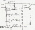
I was asked to build an LED light which consisted of 50 LED's 25 of one type and 25 of another. The reason for doing this is when you shoot someones face, depending on the light they are being filmed under conveys certain moods etc.

Anyway back to the problem. I have a microcontroller that I have producing a PWM output signal at 300mV on an oscilloscope. So I am moving onto a prototype to test the correct frequency and duty cycle of the PWM with actual LED's instead of the oscilloscope. I already have programmed the microcontroller to change the duty cycle when 2 buttons are pressed, 1 to decrease and another to increase the duty cycle.

Im confused what the best method for amplifying this small signal (300mV) to power say 12 LED's for testing and 25 for the final light.

At the moment the microcontroller is mounted on a demo board provided by the university. The PSU I have a schematic for which was provided by the university and I have all the data sheets provided for the microcontroller and the demo board.
 

Thread Starter

karmabobby

Joined Jan 20, 2009
13
Hi there. I am making an LED light that utilises a Freescale MC9S08QG8CPBE microcontroller. I already have the pwm generated however the resulting signal is very small (300mV) and I am wanting to drive 25 LED's with it (2V, 20mA)

What would be the best way to go about this amplification?

For testing I will be using an array of 12 LED's (6 in series, 2 rows in parallel)
 

Thread Starter

karmabobby

Joined Jan 20, 2009
13
Hi thanks for the info, will look into it tomorrow morning and will let you know how I get along. Dave sorry about the multiple postings in wrong place etc. Thanks guys
 

Thread Starter

karmabobby

Joined Jan 20, 2009
13
Hi. I have been thinking about this and am still really confused how to implement this into my circuit. I understand how transistors work but my course has provided precious little practical work so when it come to design, Im not great.

Im wanting to amplify the 300mV and 14.4mA to something around say if I had an array of 25 LED's

each LED 2V 20mA

5 LED's in parallel with 5 in series so to power the LED's properly I would need to have 10V and 100mA.

The main part that is confusing me is the external voltage needed to power the transistor circuit, I am guessing it would have to be more than 10V.

Im also thinking that I need to use the common emitter configutarion for this kind of amplification. This provides voltage and current gain.

If someone could provide me with some advice and possibly some links that would help me out I would be very grateful.
 

bertus

Joined Apr 5, 2008
22,270
Hello,

Can you post a schematic of the things you have upto now ?
You can have the 5 strings of 5 leds, each string must have a current limiting resistor, dependend on the power supply you want to use.
For good regulation of the current I advice to have more than 2 volts on the resistor.

Greetings,
Bertus
 

Thread Starter

karmabobby

Joined Jan 20, 2009
13
All I have to this point is a microcontroller chip that is powered by 3.3V from the prototype board provided by the university. This is mainly used for erasing and programming the EEPROM and not much else.

The microcontroller needs 3.3V to work.

It is correctly displaying the PWM on the ocilloscopes in the lab which is 1KHz with a variable duty cycle which can be increased or decreased with 2 buttons.

Im now in the process of building a prototype circuit which will have the microcontroller mounted on a piece of veroboard.

Im mainly having trouble with how to power the rest of the circuit. The PSU's in the lab have +15V 0V -15V inputs which can be varied with a knob and a current of 200mA.

This is only the prototype at the moment, the final thing will be phantom powered and have 2 arrays which can be altered by 4 buttons as the microcontroller can output 2 PWM waves both at 330mV and 14.4mA but I need to get this working.

Should I have a large input voltage, then apply it to a potential divider to provide the microcontroller with 3.3V and the rest of the circuit to have the remaining voltage. This could be the voltage applied to the BJT?
 

bertus

Joined Apr 5, 2008
22,270
Hello,

What is the amplitude of the PWM signal ?
You need to overcome the threshold (0.7 Volts) to open the transistor.
You can use the 15 Volt powersupply.
Assuming the VCEsat is 0.5 Volts, the leds are 5 x 2 Volts.
The resistor will have 15 - 0.5 - (5 x 2) = 15 - 10.5 = 4.5 Volts.
The current will be 20 mA if the resistor is 4.5 / 0.02 = 225 Ohms, nearest E 12 value is 270 Ohms.
You can hook up 5 of these strings to the transistor.
For the transistor you can take the pretty common 2N2222.
The base resistor is dependent on the voltage of the PWM, so you need to know its amplitude.

Greetings,
Bertus
 

Thread Starter

karmabobby

Joined Jan 20, 2009
13
The amplitude of the signal when the PWM is true is 330mV. When the microcontroller turns on it has a duty of 50% so an average of 115mV.

I will need the transistor to be open when the duty cycle is low. This is so I can gradually light up the LED's and dim them.

Did that answer you're question?
 
Last edited:

bertus

Joined Apr 5, 2008
22,270
Hello,

The PWM signal is very low.
What is the load on the PWM signal ?
With a microprocessor at 3.3 Volts I would expect something like 3 Volts for the PWM top to top signal.

Greetings,
Bertus
 

Thread Starter

karmabobby

Joined Jan 20, 2009
13
Ok I will look into that in the lab tomorrow, thanks for your help. I have a much clearer picture of how the circuit is going to look. So thank you very much!!!

I took the reading from the prototype board. Ill mount one on some veroboard and test it tomorrow.
 
Last edited:

Bernard

Joined Aug 7, 2008
5,784
I would use a single ended comparator operated from a 15V supply. Adjust reference to about 150mV. Inverted or non inverted output available. Add a MOSFET and drive all the LED's you wish.
 
Last edited:

Bernard

Joined Aug 7, 2008
5,784
My take. White LED's generally op. @ 3-3.5V, check V of different colors used. Use darlington transistor or MOSFET, N ch. Use bertus's guideline for stringing LED's. Note: LM339 pin3 to +15V
 

Attachments

Last edited:

Thread Starter

karmabobby

Joined Jan 20, 2009
13
Thank you very much, its a very nice solution you gave me. I will order the comparator tomorrow and will let you know how I get on.
 
Top