Facebook
 Google
 GitHub
 Linkedin
Hi,
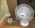
I posted in an older forum did not receive a response so I thought I should start a new thread. Where to start and keep it brief. I replaced an old 16" table fan recently that has 3 speed switches. Unfortunately, at the slowest speed switch selection, it is still too fast and loud, especially at night.
Online, I purchased several fan motor speed controls and all caused the fan to hum at very low speeds which was annoying at night. I did however, purchase a Staco 201 Variac for fan speed control and it works perfectly!
I am not convinced that there is not a solidstate solution that will provide quiet operation in a more compact form factor. After much searching this lead me to a PWM AC controller.
Adding a triangle wave generator and massaging the control circuit values, I was able to get a beautiful PWM AC controller. I am attaching a photo of the controller output and the LTSPICE circuit schematic.
All is great, right? Well, no. I measured my fan motor resistance at 263 Ohms. With that resistive I obtain the response. shown in the photo. Here's the rub: I also measured the motor winding inductance. It is 80mH and change.
When I add the inductance in series with the motor winding resistance, the simulation load voltage goes crazy - not at all well behaved and certainly not what I was wanting.
Any help from this Forum on circuit mods that would work well with the series motor inductance would be greatly appreciated.
Thanks,
Neko
Attachments
-
5.4 KB Views: 47
") ).
).