Puzzled by opamp behavior

Thread Starter

ApacheKid

Joined Jan 12, 2015
1,762
I've just started seriously exploring opamps and have a question about something I'm seeing.​

I have a 741NC fed by a split supply of +6v and -6v.

The device is setup as a basic inverting amplifier with a feedback resistor R2 of of 12K and an input resistor R1 of 3.9K, the offset-null pins are floating, there are no other components involved.

1639859690640.png

This gives a gain obviously of pretty much 3.

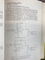
When I input a sine signal the output is as expected but as I increase the voltage of the input signal, output clipping begins but only on the -ve cycles of the output, here the input is 3v PP:

1639859308940.png

Yellow is the input, 10KHz sinusoidal.

If I increase it further then the +ve cycle also begins to clip, but the skewed nature of this puzzles me, why does clip not begin at about the same point for both -ve and +ve cycles?

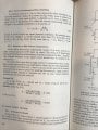
Here's the screen with the input set to 3.6v PP:

1639859878966.png

The total supply is 12v and the output is barely hitting 8v so what's going on? I verified that the supply is indeed symmetrical, each rail is 6v away from the ground, the scope's ground and the siggen's ground are all connected to that ground.
 
Last edited:

LesJones

Joined Jan 8, 2017
4,511
You will need to read the datasheet on the 741 and check the specification of how close the the supply rails the output and input pins can go. As you have not provided a schematic we have no idea how it is connected and biased.

Les.
 

Papabravo

Joined Feb 24, 2006
22,058
The 741 does not even come close to having a rail-to-rail output. Take the supply voltage and subtract 1.5 - 2.0 volts and that will be the limit of the output swing. It looks like the negative rail starts clipping at -4.0 Volts, and the positive rail still has some headroom at just over 4.0 Volts
 

Papabravo

Joined Feb 24, 2006
22,058
You will need to read the datasheet on the 741 and check the specification of how close the the supply rails the output and input pins can go. As you have not provided a schematic we have no idea how it is connected and biased.

Les.
The cut & paste piece of c**p in post #1 is supposed to pass for a schematic. It does have pin numbers, but the other connections are missing.
 

AnalogKid

Joined Aug 1, 2013
12,050
Back in the day, as in the 1960's, decent PNP transistors were very difficult to grow in an IC. For this reason, the 741 output stage is not symmetrical. It is a variation of what is called a quasi-complimentary output. This means that the headroom (the amount of voltage above and below the amplitude of the output signal, necessary for the circuit to function) is not symmetrical. The output can swing much closer to the negative rail than to the positive rail.

Often, this is implied in a datasheet operating parameters table as the difference between the maximum output signal amplitude and the power supply voltages for the test.

ak
 

LesJones

Joined Jan 8, 2017
4,511
Sorry for my error about the lack of schematic. The basic schematic together with the fact that it is supplied with a + and - 6 volt supply is enough information. You would be better using a modern op amp that more closely matches a theoretical op amp. I think the 741 design is over 50 years old.

Les.
 

dl324

Joined Mar 30, 2015
18,221
The total supply is 12v and the output is barely hitting 8v so what's going on?
Have you read the datasheet? Lightly loaded, the outputs are only guaranteed to swing to within 3V of the supplies. So the guaranteed dynamic range with +/-6V supplies is +/-3V.

1639861031049.png
1639861051556.png
 

MrSalts

Joined Apr 2, 2020
2,767
Also, you should not connect the + input directly to ground (or virtual ground). You should have a resistor that is equal to the parallel resistance of R1 and R2 to connect + input to ground (or virtual ground).
 

sghioto

Joined Dec 31, 2017
8,633
Also, you should not connect the + input directly to ground
I've never seen that before when using a dual supply in a simple amplifier as this. I did breadboard the circuit the TS posted and confirmed the negative side clipping before the positive as ak said should happen. The max output with no load was appx
9 volt p-p.
 

Thread Starter

ApacheKid

Joined Jan 12, 2015
1,762
Thanks for all the prompt replies, it was primarily the asymmetric behavior that was puzzling me, I know the 741 is a dinosaur (and no I have not yet studied the datasheet), I'm not actually building anything just slowly working through some books on op-amps to gain deeper insights.

Thanks.
 

LowQCab

Joined Nov 6, 2012
5,101
Try one of these ............
https://www.digikey.com/en/products/detail/texas-instruments/LM6142BIN-NOPB/367288
Order quick DigiKey only has 5 left !!!

Output will swing within 200mv of the Rails with a 2K Load, closer with lighter Loads.
The Inputs are also "Rail-to-Rail".
24-Volts Supply max.
Drives Capacitive-Loads as large as 1000pF at Unity-Gain without Oscillation.
Requires only a Bandwidth-Limiting-Capacitor to prevent Oscillations with sloppy designs.

It's so much less aggravation designing a Circuit with these.
.
.
.
 

Thread Starter

ApacheKid

Joined Jan 12, 2015
1,762
Also, you should not connect the + input directly to ground (or virtual ground). You should have a resistor that is equal to the parallel resistance of R1 and R2 to connect + input to ground (or virtual ground).
Where can I learn more about this? every circuit in every book I have seems to make no mention of this (at least as far as I've noticed when looking through the chapters on op-amps).

Thanks
 

MrSalts

Joined Apr 2, 2020
2,767
It's just balancing the input bias current. Not exact but it's what we used as the rule of thumb to cancel the imbalance. The op amps with jfet inputs is very low so the resistor is not needed but for a bjt input, and the op amp is not internally compensated (usually listed as "precision op amp), then the resistor is a good idea.

See attached...
 

Attachments

Thread Starter

ApacheKid

Joined Jan 12, 2015
1,762
It's just balancing the input bias current. Not exact but it's what we used as the rule of thumb to cancel the imbalance. The op amps with jfet inputs is very low so the resistor is not needed but for a bjt input, and the op amp is not internally compensated (usually listed as "precision op amp), then the resistor is a good idea.

See attached...
Most interesting, many thanks for that.
 

Thread Starter

ApacheKid

Joined Jan 12, 2015
1,762
Well here's another curiosity (due of course to my ignorance!) this is exactly the same inverting amp circuit (using the very same resistors from above) this time I found an LM324 Quad opamp in my junk box, when setup with a 20v supply (+10v and -10v) this time the clipping is less odd, but out of the box something else is present:

1639866548863.png

I just thought - the other three devices are just "floating" unconnected, I wonder if that is having some effect and causing this odd glitch.

The tech sheet says nothing about how to treat unused devices though...
 

SamR

Joined Mar 19, 2019
5,470
Commonly seen using transistors, but there is a diode fix for them. Don't know if it can be fixed with op amps since it is internal to the device?
 
Top