Put a hall effect sensor on a 120v wire? Or should I use a current transformer?

Thread Starter

zirconx

Joined Mar 10, 2010
171
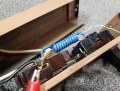
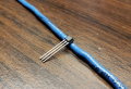
Hi, I'm interested in having my raspberry pi know if my 120v sump pump is operating. The pump draws 4A when operating. Could I detect the current with a hall effect sensor? (it's a A1120LUA-T) I'm thinking of opening up a power strip and placing a hall effect sensor in there. I'm guessing the magnetic field would not be strong enough to detect simply by placing the sensor on the wire. I have an inductor core I removed from a desktop PC, could I use that to enhance the magnetic field?

If this won't work, I'm thinking of building a current transformer using this inductor core. Or maybe buy one like this?
https://www.ebay.com/itm/5A-Sensor-...ent-Sensor-Module-For-Arduino-JG/392616824447

Or this would probably be easier to use, since it has a lot more on board circuitry. Although I don't quite understand how to use it, I don't understand the 3A/15v figure they are talking about.
https://www.ebay.com/itm/1PC-AC-Cur...Phase-Current-Transformer-Module/283534844135

I would like something small that fits inside a power strip.

Thanks.
 

Attachments

Last edited:

dendad

Joined Feb 20, 2016
4,471
The Hall sensor would need a magnetic core to help it work.
A current transformer may be easiest.
And there are slip on ones that do not require the wire to be cut.
current transformer.jpg
Just ensure the current transformer is on only one wire. The Live or Neutral, but not both.
But the modules with the electronics you show above will be ok.
 

Dodgydave

Joined Jun 22, 2012
11,301
You could use 6 1N54007 diodes, 3 in series back to back to make an AC detector this will give you 2.1V drop, then you can put a Red led with a 100 to 270 Ohms resistor across the diodes, it works perfect and can be put at the supply side instead of the pump end..DSC_0270.JPG
 
Last edited:

Reloadron

Joined Jan 15, 2015
7,515
There are a number of ways to go about doing what you want to know. All you care about is there is or is not current. I have used these little sensors in the past with great results as a simple turn key solution. They come in assorted styles and sizes illuminating when a current exceeds a preset level. Additionally the primary conductor can be looped through the center so for example a 1.5 amp threshold can have 1 amp turn through the primary wrapped twice. Much like adding loops through a regular CT (Current Transformer) as can be seen below.

60 to 5 CT 3 Turn Primary.png

The linked sensors are small, simple and ready to work. The LED line can be extended. I use them to monitor pumps and heating elements.

Also I can't tell from your images but only a single conductor (half the AC line) is the primary on a CT. Meaning if Hot and Neutral were passed through they would have a cancelling effect so would not work. I have seen the units I linked to on Amazon for $10 to $13 USD and am sure there must be others available for less off the boat.

You can also just cut the LED off and run the signal into a uC.

Ron
 

Thread Starter

zirconx

Joined Mar 10, 2010
171
The Hall sensor would need a magnetic core to help it work.
A current transformer may be easiest.
And there are slip on ones that do not require the wire to be cut.
View attachment 197312
Just ensure the current transformer is on only one wire. The Live or Neutral, but not both.
But the modules with the electronics you show above will be ok.
Thanks. I had considered one of these, I don't think I can fit this inside a power strip though. How would I use a magnetic core to "help" a hall effect sensor? Similar to my 2nd picture?

____________________________________________________________________________________

There are a number of ways to go about doing what you want to know. All you care about is there is or is not current. I have used these little sensors in the past with great results as a simple turn key solution. They come in assorted styles and sizes illuminating when a current exceeds a preset level. Additionally the primary conductor can be looped through the center so for example a 1.5 amp threshold can have 1 amp turn through the primary wrapped twice. Much like adding loops through a regular CT (Current Transformer) as can be seen below.

View attachment 197320

The linked sensors are small, simple and ready to work. The LED line can be extended. I use them to monitor pumps and heating elements.

Also I can't tell from your images but only a single conductor (half the AC line) is the primary on a CT. Meaning if Hot and Neutral were passed through they would have a cancelling effect so would not work. I have seen the units I linked to on Amazon for $10 to $13 USD and am sure there must be others available for less off the boat.

You can also just cut the LED off and run the signal into a uC.

Ron
Interesting idea... I could probably run that output to an optocoupler? I don't know what a uC is.

Could I make my own current transformer with the core I showed? I could probably only get 20 turns through there. I also have some snap on ferrite bead noise-reducing cores I could use.

____________________________________________________________________________________

You could use 6 1N54007 diodes, 3 in series back to back to make an AC detector this will give you 2.1V drop, then you can put a Red led with a 100 to 270 Ohms resistor across the diodes, it works perfect and can be put at the supply side instead of the pump end..View attachment 197318
Thank you, I would like to do something non-invasive though. I don't want to add any potential points of failure, leading to a flooded basement.
 

Reloadron

Joined Jan 15, 2015
7,515
Interesting idea... I could probably run that output to an optocoupler? I don't know what a uC is.

Could I make my own current transformer with the core I showed? I could probably only get 20 turns through there. I also have some snap on ferrite bead noise-reducing cores I could use.
uC is a micro-controller, think of it as your Raspberry Pi. :)

Another popular trick is to just place a few windings (have to experiment) around a magnetic reed switch. A magnetic reed switch can be had at just about any Lowes, Home Depot, Ace Hardware or home improvement store. The ones used for alarm systems. You can also just purchase one bare bones in a glass envelop.

Both a current loop or using a reed switch should afford good results and are non invasive.

Ron
 

Thread Starter

zirconx

Joined Mar 10, 2010
171
uC is a micro-controller, think of it as your Raspberry Pi. :)

Another popular trick is to just place a few windings (have to experiment) around a magnetic reed switch. A magnetic reed switch can be had at just about any Lowes, Home Depot, Ace Hardware or home improvement store. The ones used for alarm systems. You can also just purchase one bare bones in a glass envelop.

Both a current loop or using a reed switch should afford good results and are non invasive.

Ron
I tried that, but couldn't get it to work properly. When I used my DMM to check continuity across the reed switch, the DMM would make a loud squeal when I pulled current through the primary wire. (The DMM has an audio circuit/buzzer for continuity). So I think there is a lot of noise coming on the leads, it would probably not be good to hook that to my pi GPIO pins.

I might have too many turns here, but I use the same reed switch to indicate my backup DC pump is running. It needed 4 turns to switch on with 8A of current. Since the 120v pump uses only 4A, I will need more turns to make the reed switch turn on.
 

Attachments

Reloadron

Joined Jan 15, 2015
7,515
I tried that, but couldn't get it to work properly. When I used my DMM to check continuity across the reed switch, the DMM would make a loud squeal when I pulled current through the primary wire. (The DMM has an audio circuit/buzzer for continuity). So I think there is a lot of noise coming on the leads, it would probably not be good to hook that to my pi GPIO pins.
Thinking about it a scope would be nice to see exactly what you have. Keep in mind the difference between looking at an AC verse DC current. I am pretty sure, not positive, the small current sensors I linked to have a diode built in which drives the LED. You may want to shove a diode in there for half wave and place a cap across the output.
There are still options like using a Hall Effect I was just hoping for simple. There are module boards out there with sensors like the ACS 712 or similar.

Ron
 

Janis59

Joined Aug 21, 2017
1,846
Trafo is sure cheaper, but slower. For fast detection Hall is better however the all things needed around it from fast low-drift instrumental amplifier etc is really annoying. But when them are needed, then it are needed.
Anyway, if one may survive with ease of transformer, he ought to do it such way.
 
Top