Push ON - Push Off Circuit Identification

Thread Starter

coolcoolbeans

Joined May 31, 2019
5
This is my first time posting, apologies if there are any errors. My education is focused on more MCU based applications which is where my struggle lies for this project.

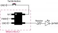
I am working on a simple wearable project that needs a push on, push off button. Unfortunately a latching button is too big for the application. In my research I have disassembled a small coin cell flashlight with a similar "push on push off" button experience (using a dome button). I am having trouble identifying an IC within the circuit so that I can replicate for my own design. Unfortunately there are no identifying logos or numbers on the part. The PCB says IC next to the component. The component has a SOT-23-5 package. I've attached a schematic of the circuit I created after inspecting the PCB.

Can you help me identify what this is? Is it a MOSFET?

Thanks for your help!
 

Attachments

djsfantasi

Joined Apr 11, 2010
9,237
BBFB5F57-9442-4BD4-9A30-D5749A3DF2D4.png So if your education has been MCU focused, why not use an MCU?

In code, it’s simple to read (and debounce) a button press. Each successive press toggles an output pin HIGH, LOW, etc...

An ATTINY45 is very small, can run on button cells, and has enough GPIO pins for your application (with several to spare).

Add a push button, LED, and a resistor and the hardware is done. I believe you can code.

The ATTiny45 can be programmed with the Arduino IDE and a USB programmer from Sparkfun for <$20 (the most expensive requirement)
 
Last edited:

crutschow

Joined Mar 14, 2008
38,506
There are several such devices. I have used the MAX16054 in an SOT23 package. It has 6 pins, not 5: https://datasheets.maximintegrated.com/en/ds/MAX16054.pdf
That should work, but you need to add a transistor buffer if you want an LED current more that a few mA (which may be bright enough for a high-brightness LED).
To get the highest LED current you need to connect the LED to the V+ and use the output as a low-side driver (LED lit when output is low).
 

jpanhalt

Joined Jan 18, 2008
11,087
That should work, but you need to add a transistor buffer if you want an LED current more that a few mA (which may be bright enough for a high-brightness LED).
To get the highest LED current you need to connect the LED to the V+ and use the output as a low-side driver (LED lit when output is low).
It enables the voltage regulator for the rest of the system, which consists of an MCU, GLCD, and thermoucouple. That keeps quiescent current to a very low level.
 

jpanhalt

Joined Jan 18, 2008
11,087
I didn't realize there would be such interest in that device. As a convenience, here is a copy of my EAGLE library for that device. Use at your own risk.

Sorry, it is a zip, but that is the only way I know to upload a folder. It was done in Eagle 7.2.
 

Attachments

Last edited:

crutschow

Joined Mar 14, 2008
38,506
Below is the LTspice simulation of a simple toggle circuit using a 4013 flip-flop.
R1-C2 provide a debounce function, preventing the FF from toggling again for about 140ms after an initial trigger.
The circuit will operate from 3V-15V.

upload_2019-6-1_12-59-57.png
 
Last edited:

djsfantasi

Joined Apr 11, 2010
9,237
I’ve not seen this particular circuit! Nice.

How do you calculate the 140ms lockout? In case I’d like to change the period.
 

crutschow

Joined Mar 14, 2008
38,506
I’ve not seen this particular circuit!
I don't remember if I saw the circuit somewhere or came up with the circuit myself, but it is a simple way to make a toggle circuit with the included debounce function.
Instead of trying to suppress the bounces as is often done, it just ignores the bounces, similar to the technique typically used for a microprocessor debounce function.
How do you calculate the 140ms lockout?
It's the time it takes the voltage to reach 1/2Vdd (the D input nominal logic threshold) or about 0.7 RC, but I used 0.6RC for some margin.
 
Last edited:

AnalogKid

Joined Aug 1, 2013
12,129
If the switch does not have to be connected to either Vcc or GND, there is a very common 2-gate or 2-transistor toggle flipflop circuit that should work.

ak
 
Top