Pulse peak value latch and aquisition

Thread Starter

Zuavirr

Joined Dec 28, 2017
25
Hello,
I am trying to find a solution for measuring fast pulse and later analysing the data:
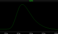
Pulse lenght is about 500ns and I need to measure each pulse individually as they will happen irregularly.
The acquisition is simple holding the peak value for 3-4us and then resetting the capacitor by mosfet.
The problem is holding and detecting peak value.
The pulses are low voltage 0-1,8V.
I have tested some solutions and they weren't precise:
The typical peak detector with diodes does not give the exact value for various pulses (linearity was very poor)
My last hope is either OPA615, but it's quite expansive and I'd like to replace it with something (equivalent)... or "comparator" peak detector circuit. I've actually found only one such application (quite old) by Maxim: https://www.edn.com/design/analog/4347624/High-speed-peak-detector-uses-ECL-comparator Comp.png
I've tried it in the simulator with other parts but it does not work. (What a surprise...)
What is best?
 

Attachments

Last edited:

Thread Starter

Zuavirr

Joined Dec 28, 2017
25
LT spice, but I can switch. I am trying to get everything using components from Linear Tech or their cheaper equivalents to keep the simulating and testing dynamic".
 

Thread Starter

Zuavirr

Joined Dec 28, 2017
25
There are additonal meas commands I used to optimize the peak to ratio noise. (obsolete now)
I just copy-pasted the circuit from the article: used fast comparator and RRIO amps but recieved no sensible response.
Maybe the problem is with the comparator ECL type? What does that ECL stand for? I couldn't find any similar parts or explanation. That is so depressing ._.
 

Attachments

ericgibbs

Joined Jan 29, 2010
18,872
hi,
ECL stands for Emitter Coupled Logic.
You may know that Common Base amps can be faster than their Common Emitter counter parts.
E

EDIT:
Your ZIP file is reading empty.?:)
 

AnalogKid

Joined Aug 1, 2013
11,056
The LM358 is not a RRIO opamp. The input common mode voltage range includes the negative rail *only*, and the output can go down close to the negative rail but not as close as a true RRIO device. Neither the input nor output can get very close to the positive rail. I'm sure Linear Tech has better parts to replace the LM358 in your circuit.

ak
 

Thread Starter

Zuavirr

Joined Dec 28, 2017
25
New ideas, new solutions, (the old topic was dead) so new topic....
I'm just desperate to get the working solution for a circuit I'm trying to finish for 5 months.
 
Last edited:

RichardO

Joined May 4, 2013
2,270
How about this, using a fast comparator for simulated inputs of 0.1V, 0.5V, 1V, & 2V:
One thing you must be aware of is that the comparator must not have diode clamps between the inputs. The symptom is that the cap holding the peak voltage will discharge through the clamp diodes toward the input voltage instead of holding the peak.

It looks like the LT1711 may be okay.
 

ebp

Joined Feb 8, 2018
2,332
Choose your hold capacitor very carefully. Tolerance is probably of no concern at all, but dielectric absorption is important for this sort of circuit.
C0G types are the only ceramics even remotely good enough. I forgot to look it up for someone else, but there is one type of surface mount plastic film capacitor that is suitable - I was thinking polymethylpentene but I'm not at all sure that is right. Some of the SM film types are really really bad. Polypropylene capacitors are low cost and good but can't take reflow temperature, so you must use through-hole types. Teflon is very good but very expensive.

ECL may be extinct - I haven't looked for several years. It was an extremely fast but very power hungry logic family that used to be used in very fast (for the day) computers. Standard supply voltage was -5.2 volts. Lots of circuits have been built using ECL line receivers, which are more or less differential-input differential-output amplifiers, as comparators. There was a newer family made for easy interface to 5 volt logic.
 

Thread Starter

Zuavirr

Joined Dec 28, 2017
25
That's a pretty nice peak detector with that comparator. (Maybe mine didn't work because I always loaded the operating point analysis)
I examined it and it works well, but the precision is as you can see on the graphs

EDIT: Does anyone know how to measure values and save them in Tina-TI?
I would like to measure the maximum value of singal, value at exact point in time (for each step) but I haven't found a solution anywhere on the net.

Linaerity (blue one peak signal input, black peak detection)
linearity.png
Delta: difference between the upper lines (peak aquisition and the real peak value )
delta.png
Hmm it driffts... I need to try the same with opa615 in Tina Ti but does it have .meas commands? Back to the simulations ;)

Circuit:
cir.png
 
Last edited:

Thread Starter

Zuavirr

Joined Dec 28, 2017
25
Hmmm, I would dream of 0,5mV as my ADC has 12bit resolution and works without modifications on range 0-1,8V (1,8V/4096~0,5mV)
Is that even possible?
 

crutschow

Joined Mar 14, 2008
34,470
Hmmm, I would dream of 0,5mV as my ADC has 12bit resolution and works without modifications on range 0-1,8V (1,8V/4096~0,5mV)
Is that even possible?
It may be possible, but extremely difficult.
If the signal ramps to 1.8V in 500ns, the peak-hold circuit must respond in 0.5mV/1.8V * 500ns = 139ps.
That requires a circuit with something like a 2.5GHz bandwidth, which is at microwave frequencies, and would require some rather exotic circuitry.
That's out of my league. :eek:

If you really need that accuracy then it likely would be better to go to a high speed A/D converter such as this to convert the pulse directly to digital and detect the peak values digitally. It will require some high speed digital circuitry but that's easier than trying to do it analog.
Linear Technology and TI also sell such high speed converters.
 

Thread Starter

Zuavirr

Joined Dec 28, 2017
25
Hmmm I guess it's time to come back to reality and accept some imperfections.
I have a RC-CR-RC shaper circuit almost ready so it should be fine to measure the peak with OPA615 or comparator after that kind of shaping.

But to compare the results between OPA615 and the comparator I need to do the measurments automatically while stepping the amplitude of the pulse...
Does anyone know is threre something similar to .meas functionality in Tina-TI?
Please help.
 
Last edited:
Top