Facebook
 Google
 GitHub
 Linkedin
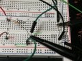
I just measured it. When the module is disconnected I measure the full of voltage of the Vcc for the signal voltage(24V). When the digital module is connected I measure 8V as I said previously.Do you have a multimeter?
If so disconnect the signal wire from the digital module and measure the signal voltage with the multimeter.
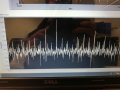
Pulse Output Flow Sensor doesn't output a Low around 0V
- Thread starter Kostas Kourbetis
- Start date