pulse machine help needed for physiotherapy

Thread Starter

ollieoscarsid

Joined Mar 18, 2018
7
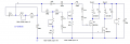
Hi all, new to the site and I need some help on a project for my physiotherapist Brother. Between us we need to create a left/right pulse circuit/machine that will assist some of his patients with walking. A kind of reminder that can be felt in the hands alternately to help move the feet.
I was thinking of using a couple of vibrating motors/cells from a mobile in a little pouch that could be held in the hands or velcroed to a walking frame etc.
It would need to be variable in frequency and duration, the little cells are 3v
I'm a mechanical engineer rather than electronic and I would like to help him out, so i thought i'd post this to see if anyone would be kind enough to suggest the circuitry involved.
Many thanks, Chris
 

BR-549

Joined Sep 22, 2013
4,931
It's hard to imagine your concept clearly. Walking frame? Please describe the functional circumstance more clearly.

ALL details. Have you a video or picture? Is there always a "walking frame"?
 
I think that you are on the right path with the piezo buzzer disks and there are many source and they are cheap - https://www.adafruit.com/product/1740?gclid=EAIaIQobChMIvuqxmrz22QIVhi-BCh2UsQBzEAQYAiABEgLTbvD_BwE or https://www.mouser.com/ProductDetai...MIvuqxmrz22QIVhi-BCh2UsQBzEAQYBSABEgKevfD_BwE

Certainly the whole circuit could be assembled on a wrist band of some sort, for example.

Tell us about the variable frequency and duration - what are the details there? What are the range of values and what determines which is used? Depending on the answer there, a cheap micro might come in handy e.g., a low end PIC like a 10F202 or a PICAXE 08M2 if that would be easier..
 
Last edited:

Thread Starter

ollieoscarsid

Joined Mar 18, 2018
7
I think that you are on the right path with the piezo buzzer disks and there are many source and they are cheap - https://www.adafruit.com/product/1740?gclid=EAIaIQobChMIvuqxmrz22QIVhi-BCh2UsQBzEAQYAiABEgLTbvD_BwE or https://www.mouser.com/ProductDetail/CUI-Inc/CEB-35D26/?qs=WyjlAZoYn53oDcwZR%2bB/vQ==&gclid=EAIaIQobChMIvuqxmrz22QIVhi-BCh2UsQBzEAQYBSABEgKevfD_BwE

Certainly the whole circuit could be assembled on a wrist band of some sort, for example.

Tell us about the variable frequency and duration - what are the details there? What are the range of values and what determines which is used? Depending on the answer there, a cheap micro might come in handy e.g., a low end PIC like a 10F202 or a PICAXE 08M2 if that would be easier..
Thanks, that's helpful. The frequency of the 'vibrations' needs to be adjustable from around 0.5-5 seconds and the duration around a similar time, always in a left/right, or one two pattern.

The whole idea is to remind a patient to put one foot in front of the other after a stroke or similar where the natural thought process has been interrupted. So they feel a vibration in their left hand which tells them to put left foot fwd etc.
Hmmm, just thinking out loud...so you could put an accelerometer (even a simple tilt switch might work) on the legs to detect a left stride for example and that would signal a buzz on the right leg...and then you would start looking for the next left stride.

Without some feedback to tell when a leg is being used, it might be a challenge to know when to buzz what. Some of that can be done inside the program without feedback - that is, always alternating buzzes, but it could become out of sync and be annoying I suppose.
 

Thread Starter

ollieoscarsid

Joined Mar 18, 2018
7
It's hard to imagine your concept clearly. Walking frame? Please describe the functional circumstance more clearly.

ALL details. Have you a video or picture? Is there always a "walking frame"?
I don't have a video, but then I'm not sure its needed really. I just need to operate two mobile phone buzzers alternately and be able to adjust the duration and frequency of the buzz's from around 0.5-5 seconds each. Kind of like a two channel metronome. Thanks
 

LesJones

Joined Jan 8, 2017
4,511
Does there need to be a gap between the pulses or will there allways be one buzzer operating..
Like this.
Left on. Left off and right comes on. Right off and left comes on. And so on.

Or
Left on. Left off. Pause. Right on. Right off. Pause. Left on. And so on.

Les.
 

Thread Starter

ollieoscarsid

Joined Mar 18, 2018
7
Hmmm, just thinking out loud...so you could put an accelerometer (even a simple tilt switch might work) on the legs to detect a left stride for example and that would signal a buzz on the right leg...and then you would start looking for the next left stride.

Without some feedback to tell when a leg is being used, it might be a challenge to know when to buzz what. Some of that can be done inside the program without feedback - that is, always alternating buzzes, but it could become out of sync and be annoying I suppose.
We think alike:), as this was something that I suggested. Apparently it's not actually needed, it seems that flashing lights are used for rehab indoors, hospitals etc which work well, but obviously you can't head towards flashing lights all the time, particularly when outside.

It's actually more for those suffering with Parkinson's, where a common problem is 'Freezing' I don't fully understand it, but it's something to do with the brain not telling the legs what to do if the thought process is interrupted. A common situation is walking through a doorway, where the person is concentrating on getting through it and forgets to walk again when on the other side, a simple left right pulse helps this. At lease that's how my Brother explained it.
 

Thread Starter

ollieoscarsid

Joined Mar 18, 2018
7
Does there need to be a gap between the pulses or will there allways be one buzzer operating..
Like this.
Left on. Left off and right comes on. Right off and left comes on. And so on.

Or
Left on. Left off. Pause. Right on. Right off. Pause. Left on. And so on.

Les.
The second one, left on, for between 0.5-5 seconds (adjustable), left off, pause for 0.5-5 seconds (adjustable) right on etc.
 

BR-549

Joined Sep 22, 2013
4,931
If you try and vibrate handle.....it will take power. If you use miniature buzzers or vibrators....you need connecting wires to patient. Are the handles on the frame isolated?

A light indicator.....or a speaker that says "right" or "left" doesn't take much power and no connecting leads. A small compartment on frame with battery will suffice.

Only one eye and one ear is needed.

If vibration is therapeutically necessary.......you might get some background here.

https://www.precisionmicrodrives.com/vibration-motors

Everything will be based on the transducer you choose.
 

-live wire-

Joined Dec 22, 2017
959
Try a microcontroller (arduino is reccomended) with some accelerometer ICs. The ICs are small and you can easily attach them to the leg. Then you would have feedback and can program it to buzz based on leg position.
 

LesJones

Joined Jan 8, 2017
4,511
Here is some code that runs on a PIC16F88 that could be modified to do what you want. As it is it sequences through 4 timed states, the time of each controlled by a potentiometer. You could just use two potentiometers, one for the pulse time and one for the pause time.
Code:
;Sequencer
;
;28/06/16
; Version 01 now being modified for 4 channels (Renamed to Sequencer_02.asm)
;


; I/O port useage

;   RA0   (Pin 17)   Analog in 0
;   RA1   (Pin 18)   Analog in 1
;   RA2   (Pin 1)     Analog in 2
;   RA3   (Pin 2)     Analog in 3
;   RA4   (Pin 3)
;   RA5   (Pin 4)     Vpp for programming
;   RA6   (Pin 15)   
;   RA7   (Pin 16)   

;   RB0   (Pin 6)     Channel 0 out
;   RB1   (Pin 7)     Channel 1 out
;   RB2   (Pin 8)     Channel 2 out
;   RB3   (Pin 9)     Channel 3 out
;   RB4   (Pin 10)
;   RB5   (Pin 11)
;   RB6   (Pin 12)   PGC for programming
;   RB7   (Pin 13)   PGD for programming


   list P=16F88
   #include p16f88.inc

;Program Configuration Register 1
     __CONFIG  _CONFIG1, _CP_OFF & _CCP1_RB3 & _DEBUG_OFF & _WRT_PROTECT_OFF & _CPD_OFF & _LVP_OFF & _BODEN_OFF & _MCLR_OFF & _PWRTE_ON & _WDT_OFF  & _INTRC_IO

;Program Configuration Register 2
     __CONFIG  _CONFIG2, _IESO_OFF & _FCMEN_OFF

; Define variables at memory locations

;*******************************************************************************
; Constants
;*******************************************************************************


RAM_START  equ  0x20


; The periods are timed with timer1 which is set to run at the internal clock
; rate (4 Mhz) of Fosc/4 or 1.0MHz which is equal to a 1 uS period.


;*******************************************************************************
; File Register Variables
;*******************************************************************************
  cblock  RAM_START

Save_STATUS     ;Save during interrupt
Save_W       ;Save during interrupt
Save_PCLATH     ;Save during interrupt
Save_FSR     ;Save during interrupt   

param1:   1  ; parameter 1  (Used in delay cycles routine)
param2:   1  ; parameter 2  (Used in delay cycles routine)

AD_Delay:   1   ;Delay count to allow AD to sample input

CH_Time:   1

AD_Channel:   1   ;AD channel number

  endc


; start at memory 0

   org   0
   goto   SETUP
   org   4
   goto   INTERRUPT


Init:
SETUP:
   clrf   PORTB     ; port B outputs low
   clrf   PORTA     ; port A output low
   bsf     STATUS,RP0   ; select memory bank 1

; set inputs/outputs
   movlw   B'00000111'   ; comparators off
   movwf   CMCON
   movlw   B'11110000'   ; port B 0 to 3 outputs 4 to 7 inputs
   movwf   TRISB     ; port B data direction register
   movlw   B'00111111'   ; outputs (0) and inputs (1)
   movwf   TRISA     ; port A data direction register
   movlw   B'11000000'   ; settings (pullups disabled TMR0/2)
   movwf   OPTION_REG

; analog inputs, A/D  

   movlw   B'00001111'   ; AN0 to AN3 are analog inputs
   movwf   ANSEL     ;Bank 1
   movlw   B'01000000'   ; left justified A/D result, VCC as ref
   movwf   ADCON1     ;Bank 1

   bcf     STATUS,RP0   ; select memory bank 0
   movlw   B'01000000'   ; Fosc  1/8 for  4MHz system clock  
   movwf   ADCON0     ; Bank 0
   bsf     ADCON0,ADON   ; A/D on
   bsf     STATUS,RP0   ; select memory bank 1
   movlw   B'01101000'   ;  for 4 MHz
   movwf   OSCCON     ; Bank 1


; Initialized Timer 1
   bcf     STATUS,RP0   ; select memory bank 0
   MOVLW   B'00110100'   ;Clock source FOSC, 1:8 prescale, Dedicated Timer1 oscillator circuit disabled,
  ;Do not synchronize external clock input, Fosc/4 Timer off
         ;So counter will increment every 8 uS  (4 Mhz clock)
         ; So for overflow after 500 ms (62500 * 8uS ) counter would need to be loaded with 0x0BDC

   MOVWF   T1CON     ;With 4 Mhz clock timer will increment every 500 mS


START:

Main_Loop:

Time_CH0:
   BSF   PORTB,0     ;1 cycle  (Set channel 0 output)
   MOVLW   0x00     ;Select channel 0
   MOVWF   AD_Channel   
   CALL   Read_Analog
   CALL   Channel_Delay
   BCF   PORTB,0     ;1 cycle  (Clear channel 0 output)


Time_CH1:
   BSF   PORTB,1     ;1 cycle  (Set channel 1 output)
   MOVLW   0x01     ;Select channel 1
   MOVWF   AD_Channel   
   CALL   Read_Analog
   CALL   Channel_Delay
   BCF   PORTB,1     ;1 cycle  (Clear channel 1 output)


Time_CH2:
   BSF   PORTB,2     ;1 cycle  (Set channel 2 output)
   MOVLW   0x02     ;Select channel 2
   MOVWF   AD_Channel   
   CALL   Read_Analog
   CALL   Channel_Delay
   BCF   PORTB,2     ;1 cycle  (Clear channel 2 output)


Time_CH3:
   BSF   PORTB,3     ;1 cycle  (Set channel 1 output)
   MOVLW   0x03     ;Select channel 3
   MOVWF   AD_Channel   
   CALL   Read_Analog
   CALL   Channel_Delay
   BCF   PORTB,3     ;1 cycle  (Clear channel 1 output)

   GOTO   Main_Loop


;     -----------------------------------------------------

; Interupt handler  (Interrupts not used.)

INTERRUPT:
;Save various registers

   MOVWF Save_W     ;Save W   
   MOVF STATUS, W   
   CLRF STATUS      ;Bank 0 will be selected
   MOVWF   Save_STATUS
   MOVF   PCLATH, W
   MOVWF   Save_PCLATH
   MOVF   FSR, W
   MOVWF   Save_FSR


;Restore registers

   MOVF   Save_FSR, W
   MOVWF   FSR
   MOVF   Save_PCLATH, W
   MOVWF   PCLATH   
   MOVF   Save_STATUS, W   
   MOVWF    STATUS  ;Restore STATUS   
   SWAPF    Save_W, F   
   SWAPF    Save_W, W  ;Restore W   
   RETFIE

;     -----------------------------------------------------
;Subroutines

Read_Analog:       ;Channel number will be in AD_Channel (Bits 0 - 2)
         ;Result returned in "W"

   RLF   AD_Channel   ;Move bits to required position (Bits 5 -3)   ;1 cycle
   RLF   AD_Channel   ;1 cycle
   RLF   AD_Channel   ;1 cycle
   BCF   ADCON0, 3   ;1 cycle
   BCF   ADCON0, 4   ;1 cycle
   BCF   ADCON0, 5   ;1 cycle
   MOVF   AD_Channel, W   ;1 cycle
   IORWF   ADCON0, F   ;Select channel   ;1 cycle

   MOVLW   D'40'     ;1 cycle       64 decimal
   MOVWF   AD_Delay   ; acquisition time  1 cycle

Dec_AD_delay:             ;loop is 3 cycles long (64 x 3 = 192
   DECFSZ   AD_Delay,f   ;1 cycle  (2 on exit)
   GOTO   Dec_AD_delay   ;2 cycles
   BSF     ADCON0,2     ; GO/DONE bit start conversion
WAIT_AD_Ready:
   BTFSC   ADCON0,2     ; conversion complete when cleared ~11 cycles
   GOTO   WAIT_AD_Ready
   MOVF   ADRESH,w
   RETURN     ;2 cycles


Channel_Delay:
   MOVWF   CH_Time   ;1 cycle
   INCF   CH_Time   ;So that AD value of zero does not give maximum time

CH_Loop:
   DECFSZ   CH_Time   ;1 cycle (2 cycles on exit)
   GOTO   CH_Delay
   GOTO   CH_End

CH_Delay:     ;This generates one unit of channel delay
;   CALL   DELAY_100mS   ;100mS * 256 =25.6 seconds
;   CALL   DELAY_50mS   ;50mS * 256 =12.8 seconds
   CALL   DELAY_20mS   ;20mS * 256 = 5.12 seconds

   GOTO   CH_Loop

CH_End:
   RETURN     ;2 cycles


Delay:

DELAY_100mS:
; Value for param = (100000 - 14)/8 = 99986/8 = 12498 = 0x30D2

   MOVLW   0x30     ;   (1 uS)    (1 cycle)
   MOVWF   param2     ;   (1 uS)    (1 cycle)
   MOVLW   0xD2     ;   (1 uS)    (1 cycle)
   MOVWF   param1     ;   (1 uS)    (1 cycle)
   GOTO   delay_cycles

DELAY_50mS:
; Value for param = (50000 - 14)/8 = 49986/8 = 6248 = 0x1868

   MOVLW   0x18     ;   (1 uS)    (1 cycle)
   MOVWF   param2     ;   (1 uS)    (1 cycle)
   MOVLW   0x68     ;   (1 uS)    (1 cycle)
   MOVWF   param1     ;   (1 uS)    (1 cycle)
   GOTO   delay_cycles     ;Not needed as delay_cycles follows on from here.

DELAY_20mS:
; Value for param = (20000 - 14)/8 = 19986/8 = 2498 = 0x09C2

   MOVLW   0x09     ;   (1 uS)    (1 cycle)
   MOVWF   param2     ;   (1 uS)    (1 cycle)
   MOVLW   0xC2     ;   (1 uS)    (1 cycle)
   MOVWF   param1     ;   (1 uS)    (1 cycle)
;   GOTO   delay_cycles     ;Not needed as delay_cycles follows on from here.

;*******************************************************************************
; Function:  delay_cycles
; Description: Delay a specified number of instruction cycles including
;  interrupt cycles.  The function call overhead adds between
;  13 and 16 cycles of delay on top of the specified value.
; With 4 Mhz system clock and 1:8 prescale
;Delay will be  param * 2 uS + (13 * 1uS)  + 0 to 3 uS
;     = param * 8 uS + (13 to16.0 uS)  (Use 14 uS for calculation.)
;  So param = No. of (uS-14)/8
; Parameters:  param1 - least significant byte of 16 bit cycle delay
;  param2 - most significant byte of 16 bit cycle delay
; Returns:  None
;*******************************************************************************
delay_cycles:
  comf  param1,F  ; negate the delay by complementing the     (1 uS)    (1 cycle)
  comf  param2,F  ; low and high bytes         (1 uS)    (1 cycle)
  bcf  T1CON,TMR1ON  ; stop timer 1           (1 uS)    (1 cycle)
  movf  param1,W  ; move the low byte of the delay into     (1 uS)    (1 cycle)
  movwf  TMR1L  ; timer 1           (1 uS)    (1 cycle)
  movf  param2,W  ; move the high byte of the delay into     (1 uS)    (1 cycle)
  movwf  TMR1H  ; timer 1           (1 uS)    (1 cycle)
  bcf  PIR1,TMR1IF  ; clear the timer 1 rollover flag     (1 uS)    (1 cycle)
  bsf  T1CON,TMR1ON  ; turn on timer 1         (1 uS)    (1 cycle)
   
tmr1_check:   
  btfss  PIR1,TMR1IF  ; wait for the timer 1 rollover flag to     1 uS while looping    (2 uS) (2 cycle) on exit
  goto  tmr1_check  ; trigger
  return         ;             (2 uS)   (2 cycle)


   END
It could be modified to run on a more modern PIC if required.

Les.
 

DickCappels

Joined Aug 21, 2008
10,661
Just curious, how many of these devices do you imagine will be built, and do you think that using programmable parts to reduce parts count will be an advantage in your case?
 

128ITSH

Joined Jul 20, 2017
101
I think the best option for vibration would be a piezo (like Raymond Genovese advised).
The reasons are:
- It is small and flat so you can attach it to the patient's hand without too much complexity, as opposed to vibration motors which will probably require special enclosure in order to attach it to the hand.
- I guess it takes less power than a motor.
- It is cheaper than a motor.
A question to you: Where exactly does the vibrating part should be on the patient's hand? by hand do you mean the fist, or could it be higher on the arm? I'm asking this because it will probably be easier on the arm.
 
Top