 Facebook
 Google
 GitHub
 Linkedin
Hello,
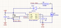
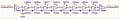
I have assembled an LED driver design (based on the PT4121E IC) powered at 48V from an IRM-60-48 source on a breadboard. Each driver controls a different branch of LEDs. The driver I am using for testing controls a branch of 8 UVA 395nm LEDs (G3535N1UVS8U06 395NM), which are located on a second PCB. The purpose of the driver is to receive a PWM signal from an Arduino, in my case at 500Hz, which allows me to regulate the LEDs from 0 to 100%. The circuit adjusts the branch current to about 666mA using a 0.3 ohm resistor. Attached are the schematics for both the driver and the LED branch.
I am experiencing problems when controlling the LEDs. I have managed to get the LEDs to dim correctly for a short time, but then they fail and start to flicker. I have seen in a test that changing the MOSFET (I am using an SI2308A, SOT-23) solved the problem momentarily, so I assume that it ends up failing. I have also seen that the driver IC gets very hot, reaching almost 100ºC, which is not a good sign.
I would appreciate any possible ideas or solutions.
Code:
const int pwmPin = 4; // Pin GPIO del ESP32-S3 conectado a UVA2 (Pin DIM)
const int pwmFreq = 500; // Frecuencia PWM de 2 kHz
const int pwmResolution = 8; // Resolución de 8 bits (valores de 0 a 255)
const int pwmChannel = 0; // Canal PWM virtual
void setup() {
// Inicializamos el puerto serie a 115200 baudios
Serial.begin(115200);
// Damos tiempo a que se abra el monitor serie
delay(1000);
Serial.println("\n--- TEST MANUAL DRIVER PT4121E ---");
Serial.println("Escribe un porcentaje (0 a 100) y presiona Enter:");
// 1. Configuramos el canal PWM
ledcSetup(pwmChannel, pwmFreq, pwmResolution);
// 2. Asociamos el canal al pin
ledcAttachPin(pwmPin, pwmChannel);
// Apagamos los LEDs por seguridad al iniciar
setDimming(0);
}
void loop() {
// Comprobamos si has escrito algo en el Monitor Serie
if (Serial.available() > 0) {
// Leemos el número que has escrito
float porcentajeDeseado = Serial.parseFloat();
// Limpiamos el "Enter" (\n o \r) que se queda en el buffer
while(Serial.available() > 0) {
Serial.read();
}
// Mostramos confirmación en pantalla
Serial.print("Ajustando brillo al: ");
Serial.print(porcentajeDeseado);
Serial.println("%");
// Aplicamos el nuevo brillo
setDimming(porcentajeDeseado);
}
}
// =================================================================
// Función auxiliar para controlar la rama LED por porcentaje
// =================================================================
void setDimming(float percentage) {
// Limitar los valores para no volver loco al PWM
if (percentage < 0.0) percentage = 0.0;
if (percentage > 100.0) percentage = 100.0;
// Mapear el porcentaje (0-100) al ciclo de trabajo (0-255)
int dutyCycle = (int)((percentage / 100.0) * 255.0);
// Mandar la señal al driver
ledcWrite(pwmChannel, dutyCycle);
}
Attachments
-
 40.6 KB Views: 14
 -
 7.9 KB Views: 13


